I have a strange issue in my lab with four STARs with sequential serial numbers that are having issues detecting liquid (water) using the G11/H12 channels of the MPH. We have no issue detecting liquid with A1/B1 and the issue persists across different labware types and labware columns. Additionally we’ve dialed up cLLD sensitivity but that didn’t work either
We’ve been able to diagnose the issue to the cLLD signal from the right side of the MPH are just lower than on the left side, so the threshold isn’t being triggered. What’s more is we’ve had the trace/wire replaced and the channels replaced and the problem still occurs!
Has anyone else run into this? The fact that these instruments were manufactured right after another has me worried that this could be a mfr defect or maybe some initial firmware setup was missed. Curious about if any of the Hamilton folks in this forum know of any settings that could modify the cLLD signal from each MPH probe, sort of like a gain multiplier, that could be used to calibrate the signals to a common value. Either that or any other settings or tweaks that could help!
Hi @evwolfson ,
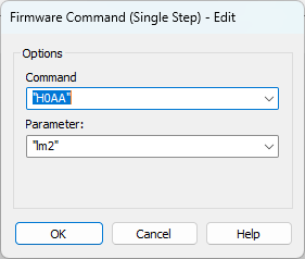
Have you tried setting the cLLD channel for the MPH? Send the following firmware command after initializing the system.
This should be the default (will accept cLLD of A1/B1 OR G11/H12).
2 Likes
Thanks for the info, but not sure if that will help us. I should have specified our use case.
We are aspirating ~200 uL from a 96 well plate, probably around 1000 uL well capacity. Running 96 samples we have no problem detecting liquid and triggering the aspirate. However, with less than 96 samples we offset on the right hand side of the head - so column 1 would be empty if we have 88 samples. When running less than 96 samples we’re relying on the G11/H12 signal but it’s just simply a less intense signal than we receive on the A1/B1 so the cLLD trace never crosses the threshold and we get liquid not detected error.
We’ve also looked at aspirating from the same column of the labware when mounting 8 tips on col 1 vs col 12 and the no liquid detected error happens every time when tips are mounted on col 12. Furthermore, we also tested some different labware types (trough , etc) and volumes and we were able to detect liquid using just the 8 tips on the 12th column in something like a trough, but just not with the actual labware in use.
Hi @evwolfson
Sorry to hear that your MPH is having capacitance detection sensitivity issues. MPH has nuance for LLD so I’ll share some lore.
The two probe sets with detection capability (A1/B2 and G11/H12) are tethered to the same detection lead. Meaning A1 and B2 use their cumulative capacitance load as a single signal (same with the other probe set). My assumption is that each lead is tethered to separate processors managing separate detection circuits and monitoring. If they were interfering with eachother, I’d imagine they’d both fail.
Anyways, my gut tells me it’s an electronics issue with the components managing the LLD circuit for G11 and H12 and will require some level of service intervention.
That said, if you are able to post screenshots of the LLD traces for A1 and H12 respectively? From your post it seems clear you know how to access these plots. If so, I can follow up with engineering to see if they have a more specific follow up, but it’s likely that something will need to be replaced.
Is the starting signal frequency for G11H12 lower than the other probe set? Or is the reduction in signal at liquid contact lower?
Thanks.
-Nick
2 Likes
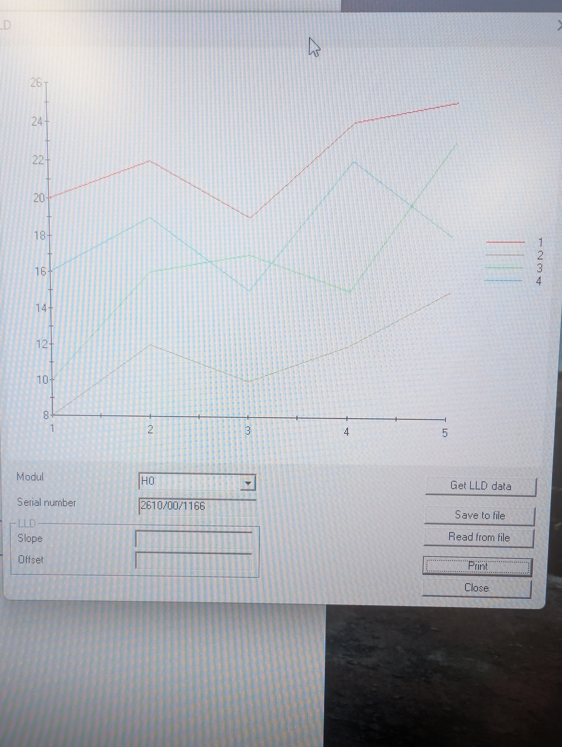
Here’s the plot, but I have no idea what units or anything are on here - even which series is which channel. I just labeled them sequentially as they appear in the dataset.
Phone picture was the easiest way to share the info.
1 Like
That’s just the default plot that renders when you open the LLD viewer. I agree it isn’t helpful or intuitive.
When you select the button ‘Get LLD data’ firmware will retrieve the latest LLD dataset in the memory buffer, from the last time a cLLD-related command was used. This data will also be erased when powering the system off. In short:
- Run a test method to aspirate 0uL (with LLD enabled) from a trough or a fully filled 96 wellplate of uniform volume. Eject tips to pickup position and end of method, let connection terminate
- Pull LLD data using the GetData button with H0 specified
Full disclosure - I have only used this tool for channels before, so there may be some nuance to isolating which data set is reported. Im not 100% sure if the tool will only plot one probe set curve, and if that is the case it might not be clear which of the two it is. If this is the case I suspect youll need to run the above procedure twice, using H0AAlm0 and H0AAlm1 prior to the aspiration respectively per each test run.
Apologies, that I missed that this was happening on numerous systems manufactured at the same time. Once service intervenes we can report this to our quality department to investigate.
Thanks.
-Nick
1 Like
Service has already been very helpful with diagnosing these issues, but being the curious soul that I am, I also wanted to take a crack at understanding what was going on and how to best mitigate it in the future (if possible).
I’ll see if I can replicate your procedures and if the plots are a bit more clear.
1 Like