Author: Joseph Rodriguez, Peak Robotics - Grenova, jrodriguez@grenova.com
Date: 27 May 2026
https://peakrobotics.com/
Foreword:
Carousel Manual Jog Switch — E-Stop Conversion Guide with instructions created by Patrick Moreland (Primary Engineer and Director at Peak Robotics). This article was authored by Joseph Rodriguez, who may be used as the point of contact for questions related to this family of products.
Document: TN-Carousel-Estop-001 Product: Peak Robotics CS6 / CS10 Carousel PCB Reference: 61104001, Rev. A Software Manual Reference: PSM-102 Rev. 3 Installation Manual Reference: PSM-101 Rev. 1
Publishing log
- 27May26, initial publication retracted to due to formatting issues in article. Republished with formatting corrected.
Overview
This article explains how to convert the Input 4 (white wire) of the standard Manual Jog Switch into a dedicated emergency stop (e-stop) input. After this modification, the carousel motor will be immediately disabled when the e-stop circuit is triggered, and the jog switch will only function for single-direction (forward) jogging.
![]() Warning: The CS6/CS10 Carousel is capable of generating enough force to cause injury. PAA recommends the Carousel be mounted inside an enclosure with safetyinterlocked doors or light curtains. This modification directly addresses the factory limitation noted in PSM-101 §3.3: “The Carousel is not equipped with an emergency stop button.”
Warning: The CS6/CS10 Carousel is capable of generating enough force to cause injury. PAA recommends the Carousel be mounted inside an enclosure with safetyinterlocked doors or light curtains. This modification directly addresses the factory limitation noted in PSM-101 §3.3: “The Carousel is not equipped with an emergency stop button.”
![]() Caution: Disconnect power to the Carousel before performing any wiring work. All internal voltages are 24 VDC or less, but voltage potential can damage sensitive components.
Caution: Disconnect power to the Carousel before performing any wiring work. All internal voltages are 24 VDC or less, but voltage potential can damage sensitive components.
Background: How the Standard Jog Switch Works
Understanding the factory jog switch circuit is essential before making any modifications. The following describes the default behavior as wired on PCB 61104001, Rev. A.
Connector and Wire Map The Manual Jog Switch (assembly 61111006) connects to the PCB via a 3-pin Molex connector (61111007). The three wires are:
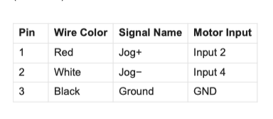
Forward Jog (Red Wire — Input 2)
When the jog switch is pressed in the forward direction, the red wire pulls Input 2 to ground. This triggers a program bank stored on the motor that advances the carousel one station in the positive (forward) direction.
Reverse Jog (White Wire — Input 4)
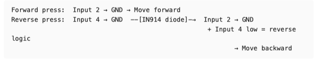
When the jog switch is pressed in the reverse direction, the white wire pulls Input 4 to ground. A diode (IN914) on the PCB simultaneously pulls Input 2 to ground as well, so the same forward-direction program bank is triggered. However, a logic statement inside that program bank checks the state of Input 4: if Input 4 is grounded, the direction is reversed, causing the carousel to advance one station in the negative (reverse) direction.
The Diode’s Role
The IN914 diode on the PCB is the critical component that links the Input 4 signal back into the Input 2 program bank trigger. This diode must be disabled before Input 4 can be repurposed as an e-stop, because otherwise triggering the e-stop circuit would simultaneously command a carousel move.
Note on Newer Carousels: Newer PCB revisions include a small switch on the board that can be flipped to deactivate the diode without physically cutting it. Consult the board silkscreen to identify this switch. The schematic (Rev. A) does not show this switch. Required Tools and Materials
Small wire cutters or flush cutters (for diode lead removal on Rev. A boards) Wire strippers Soldering iron (if permanently reconnecting wires) E-stop switch rated for the intended application (normally-open contact, momentary or latching as preferred) Serial Port Debugger software (download: Box) USB-to-Serial adapter (FTDI chipset recommended; included with Carousel) Multimeter (for verification)
Modification Procedure
Step 1 — Power Down the Carousel
Disconnect the 24 VDC power supply from the carousel connector panel before performing any hardware modifications. Confirm power is off by verifying the blue Power Status LED is no longer illuminated.
Step 2 — Disable the IN914 Diode
The IN914 diode is located on the connector board (PCB 61104001) inside the actuator. It bridges the Input 4 signal back to the Input 2 motor input.
On Rev. A boards (no onboard switch):
-
Locate the IN914 diode on the PCB. It is shown in the schematic on the Manual Jog signal path, between the Jog− line and the Input 2 motor signal line.
-
Using flush cutters, snip one lead of the diode to open the circuit. Either lead may be cut; cutting the leg closest to the board edge is typically easiest.
-
Confirm the cut with a multimeter set to continuity — there should be no continuity between the Input 4 line and the Input 2 line through the diode path after the cut.
On newer boards (with onboard switch):
-
Locate the small DIP switch on the PCB (check silkscreen label).
-
Flip the switch to the diode-disabled position.
-
No soldering or cutting required.
 Caution: Do not remove the diode entirely unless necessary — a single snipped lead is sufficient and preserves the option to restore factory behavior.
Step 3 — Rewire the White Wire (Input 4)
With the diode disabled, Input 4 is now electrically isolated from Input 2 and can be repurposed.
-
Disconnect the white wire (Pin 2) from the jog switch assembly.
-
Connect the white wire to one terminal of your e-stop switch circuit.
-
Connect the other terminal of the e-stop switch to the ground (black wire / Pin 3) of the carousel 3-pin connector — this is the same GND reference used by the rest of the jog circuit.
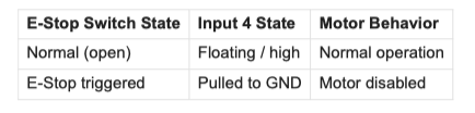
The resulting circuit behavior is:
Note — Inverted Logic Option: If your safety system requires the circuit to be grounded during normal operation and open during an e-stop (fail-safe/normally-closed topology), see the Optional Inverted Logic section at the end of this document before proceeding to Step 4.
Step 4 — Configure Input 4 as E-Stop in the Motor Firmware
The motor’s onboard controller must be told that Input 4 is now an emergency stop signal rather than a jog direction input. This is done by writing a parameter directly to the motor using the Serial Port Debugger.
Connection Setup
-
Connect the Carousel to the PC via the RS-232 serial cable and the supplied USB/Serial adapter.
-
Power on the Carousel.
-
Open Serial Port Debugger.
-
Select the correct COM port. 5. Set the BAUD rate to 57600 bps.
Send the E-Stop Configuration Command
In the Serial Port Debugger terminal, send the following command:
k27=7200
This writes the value 7200 to motor parameter k27 , which configures Input 4 as an emergency stop input. When Input 4 is pulled to ground, the motor will immediately disable.
![]() Important: This command writes to the motor’s EEPROM. Do not send k parameter commands unnecessarily — the EEPROM has a limited number of allowable write cycles. Only send this command once during the initial configuration.
Important: This command writes to the motor’s EEPROM. Do not send k parameter commands unnecessarily — the EEPROM has a limited number of allowable write cycles. Only send this command once during the initial configuration.
Step 5 — Verify the Modification
Before putting the system back into service, verify each aspect of the modification:
-
E-Stop Test: With the carousel powered and initialized, trigger the e-stop switch. The motor should disable immediately. Confirm by attempting a software-commanded move — it should fail and return an error.
-
Forward Jog Test: With the e-stop switch in its normal (open/safe) state, press the jog switch in the forward direction (red wire side). The carousel should advance one station forward.
-
Reverse Jog Test: With the e-stop in its normal state, press the jog switch in the reverse direction (white wire side — now disconnected from the e-stop and not connected to Input
4). The reverse jog will no longer function. This is expected behavior — see note below.
![]() Known Limitation: After this modification, the manual jog switch operates in one direction only (forward). The reverse jog function is permanently sacrificed to provide the e-stop input. If bidirectional manual jogging is still required, a separate two-button pendant wired only to Input 2 (with a software-toggled direction bit) would need to be developed.
Known Limitation: After this modification, the manual jog switch operates in one direction only (forward). The reverse jog function is permanently sacrificed to provide the e-stop input. If bidirectional manual jogging is still required, a separate two-button pendant wired only to Input 2 (with a software-toggled direction bit) would need to be developed.
Step 6 — Re-enable the Motor After an E-Stop Event
When Input 4 is triggered (e-stop activated), the motor is disabled and will not respond to move commands until it is re-enabled via software. To re-enable the motor after an e-stop event, call the Initialize() method from the PeakCarouselControl.dll :
ReturnValue = Carousel.Initialize(ParameterFileName, False, False)
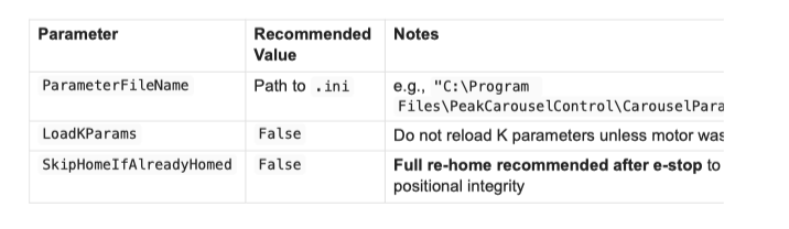
On SkipHomeIfAlreadyHomed : A full re-home ( False ) is recommended after an e-stop
event because the motor encoder state may be uncertain following an uncontrolled stop. If your application requires minimizing re-home time, you may set this to True — the DLL will check whether the encoder position was reset and only home if needed. However, this introduces a risk of positional drift if the carousel was moving at the time of the e-stop.
Tip for Robust Driver Code: A well-implemented host application should listen for the CarouselError event (PSM-102 §9.3), check the returned ErrorCode , and — if the code indicates a motor disabled state — prompt the operator to clear the e-stop condition before calling Initialize() . This prevents accidental re-initialization while the safety condition is still active.
Optional: Inverted Logic (Normally-Closed E-Stop)
In some safety-circuit topologies, the e-stop signal line is held at ground during normal operation and opened (disconnected from ground) to trigger an e-stop (a fail-safe approach where a broken wire triggers the stop).
To configure this inverted behavior, send the following additional command via Serial Port Debugger at 57600 BAUD:
k26=1000
![]() Side Effect: The k26 parameter also affects the direction logic used by the jog switch program bank. Because the remaining jog switch function (forward jog via red wire / Input 2) bases its direction on the state of Input 4, sending k26=1000 will invert the jog direction as a side effect. Factor this into your testing and documentation if you use this option.
Side Effect: The k26 parameter also affects the direction logic used by the jog switch program bank. Because the remaining jog switch function (forward jog via red wire / Input 2) bases its direction on the state of Input 4, sending k26=1000 will invert the jog direction as a side effect. Factor this into your testing and documentation if you use this option.
Summary of Changes

Related Documents
-
PSM-101 Rev. 1 - Carousel Installation Instructions (CS-06 & CS-10)
-
PSM-102 Rev. 3 - CS6 & CS10 Carousel Software Manual
-
61104001 Rev. A - Carousel PCB Schematic
-
Serial Port Debugger - https://app.box.com/v/SerialPortDebugger
Tags
#carousel #peak-robotics #CS10 #safety
#hardware
#e-stop
#jog-switch
#PCB
#wiring
#CS6