good definitions should be shareable, and the edits of labware over time should follow a logarithmic curve, but would be very curious to use Camillo’s CMM hack for automated labware definitions. Wonder if it’s worth the time. Good definitions seem important for getting a baseline working, and crucial for working with PLR’s relative location representation. Offsets after perfect definitions must result from manufacturing inaccuracies, and I agree that having a tool is potentially valuable (depending on variance between theoretically identical labwares).
Does this mean you have to generate 2 different definitions for the same plate when it is moved to a different location (e.g. with the iSWAP)?
I agree that every user is likely to have to make small changes to make their labware definitions perfect.
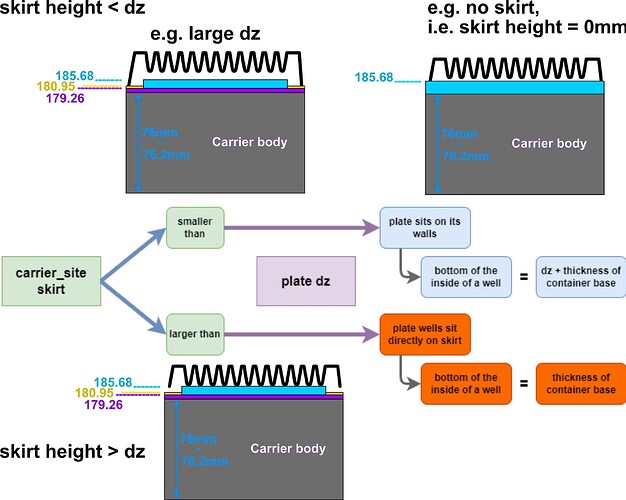
However, the problem at the moment is that due to missing information the current definition architecture breaks apart in certain situations (when carrier_site_skirt < dz).
In these situations the exact same plate definition that works perfectly on a carrier_site with a skirt currently leads to crashes on a carrier_site without a skirt.
An automation infrastructure cannot work if the correct plate definition leads to automation protocols crashing, both physically and programmatically (due to the resulting Z drive error).
This means the question here is not about optimising/perfecting labware definitions, instead it is about how to not make the liquid handler crash into a plate that is perfectly defined.
I agree; there is always some variation, e.g. plate manufacturing inaccuracies, slight tilts on the robot arm, unevenness in the carrier_site plate … that’s why we need tolerances (and a system to track them like GD&T), and like you said, Rick, there should be a logarithmic curve of post-merge definition adjustments - but that is actually how semi-universal definitions can actually be achieved: by cross-validation and iterations executed by teams across the globe, something that PLR can achieve while proprietary control systems are too locked up.
But the important part is that no definition added to the PLR resource library leads to a crash when someone new tries them out.
Slight bending of the tip or maybe a bit more distance between the tip and the bottom of a well, that’s okay and can be corrected by the individual user.
But these skirts are 4-8 mm tall. No tolerance can account for such a big error and it leads to serious crashes.
Knowing this, we cannot leave the physical definitions incorrect.
How about introducing an offset attribute for each Resource?
Right, this auto calibration seems slightly tangential to the main topic of this thread (skirts), but in this thread we do need to figure out how to get the skirt information since that is not in the venus labware database.
- how dz is used in tipracks
I imported the dz in the same way as I did dz for plates: from the Cntr.1.base property in hamilton rck files. This presumably refers to the base of the tip rack when it contains tips (judging by the fact that dz=-83.5 for HTF, -22.5 for LTF). In STAR.pick_up_tips, the tip length is added to the base location of tipspots:
    max_z = max(op.resource.get_absolute_location().z + \
                 (op.offset.z if op.offset is not None else 0) for op in ops)
    max_total_tip_length = max(op.tip.total_tip_length for op in ops)
    max_tip_length = max((op.tip.total_tip_length-op.tip.fitting_depth) for op in ops)

...

        begin_tip_pick_up_process=int((max_z + max_total_tip_length)*10),
        end_tip_pick_up_process=int((max_z + max_tip_length)*10),
This is slightly silly and can probably be redone smarter. Again, when writing the STAR backend and initial PLR version, I just imported the numbers from the base files and figured out how they mapped onto firmware command. Then I gave them names that make sense from that perspective. It was not designed from first principles considering other robots, so there is probably good room to refactor.
- how the coordinate information for aspiration/dispense is being called? (i.e. going backwards from the aspirate/dispense command all the way to the original definitions of the resources and labware)
get_absolute_location is called in HamiltonLiquidHandler._ops_to_fw_positions (HamiltonLiquidHandler is the shared base between STAR and Vantage).
To my understanding, that is the carrier_site skirt_height?
A class variable that represents the real, physical offset that different sites exhibit.
However, if encoded in this variable, then plate definitions can programmatically adapt to them in the exact same way that they do physically, i.e. using logic that accounts for their interaction.
VENUS does this, because the same plate definition works on different carrier_site types. VENUS just walks around the logic problem by hard-encoding whether a plate-carrier_site interaction is “rack”-based or “container” based, which we don’t think makes sense for adaptive programming and therefore have to find a way around it.
I agree, but I don’t think this information has a “ground truth” for the same reason I mention above why VENUS is the way that it is (to my understanding).
Therefore, I cannot see another way around this but to make all carrier_site skirt_height=0 and people who know how to measure the skirt_height can update their carriers as they go along.
That way is slow, I agree, but it is precise, can be executed concurrently (both asynchronously as well as in parallel)… and even if nobody would ever change the default skirt_height=0 of a carrier that actually has a skirt, it wouldn’t change anything to the way things are right now. This means there is nothing to lose but a lot to gain ![]()
Unfortunately, I have to disappoint here: my retrofit of the STAR as a CMM is limited to only conductive materials.
This means it works amazingly to identify carrier height, flatness, skirt_height, or any module specifications - in the z dimension only (I haven’t found the time yet to expose the x- and y-dimension alternative, which do exist).
Importantly, this means one cannot use the probe_z_height_using_channel function to probe plates, because they are all made of highly electrically resistant materials like polystyrene, polypropylene and polycarbonate → the STAR doesn’t detect them using cLLD and crashes into them.
If I find the time I’d love to investigate further how lld_mode=4, aka “crash into the bottom”, actually works → because this is the key to getting automated definitions of non-conductive plates in my view.
Because we know that lld_mode=4 must store the information of the “soft crash”; all we want is that same information. But that is a conversation for a different thread ![]()
I proposed adding an offset for Ben’s use case of small, setup-specific resource calibrations. The skirt_height should be properly named.
Exactly. We might even consider raising a NotImplementedError when we don’t have a skirt_height yet.
Could the CMM be used to move down, then up by the smallest possible delta, then to the sides?
I think I will then leave the tip racks alone, at least for the moment.
I am just focusing on the carrier z-height issue, which seems to only affect plates.
But in general, since PLR has made now loads of design decisions that deviate from VENUS, we must revisit these direct imports. They were clearly the way to go to get started but as we learn more about what computational changes we want and need to make we have to go back to these imports and update them.
I checked, I believe thoroughly, and I could only find the x and y coordinate to be called by this method inside liquid_handling/backends/hamilton/base.py.
Do you know where is the z coordinate called?
I found that dz is generated by create_equally_spaced in resources/itemized_resource.py where the docstring states:
    """
    dx: The bottom left corner for items in the left column
    dy: The bottom left corner for items in the top row
    dz: The z coordinate for all items
   """
…which we now, of course, know is a heavily oversimplification, and wrong in some cases.
We need to figure out how the information is transferred from this initial definition to the final firmware command being sent to the machine.
I think that is a great idea. It forces people to add the correct value and thereby also acts as a safety for the machine to prevent crashes.
In theory, yes.
There are just a couple of considerations:
- Does one use a conductive material → that excludes all plastic labware, i.e. is only useful for some metals … though I always wanted to place a microtiter plate into a sputterer, coat it with a layer of palladium or gold and see whether it is now conductive, but I’d need to design a specialised sputterer holder for it …

- There is a firmware command for search for cLLD when moving in the y-direction, but a.) it searches “in steps” not in terms of absolute location which makes writing a wrapper a bit more cumbersome, and b.) I haven’t fully figured out the firmware command and don’t know how to set it to go in the negative y-direction (towards the origin).
- I haven’t found an equivalent x-search firmware command yet.
sorry for the late response.
100%
importing ancient design decisions from elsewhere is not first-principle optimization, which is what we need. At the same time, I found it exceedingly helpful to be able to run a script after I make a change to the PLR labware model, and automatically rewrite all definitions. It’d be good to maintain this as long as we can. For information not in venus, like skirt height, perhaps the resource-maker script can look at current PLR definitions to extract the extra information, and use that for rewriting.
z is not in there, correct.
the z-coordinate of aspirations/dispenses actually determines multiple parameters of the operation:
- minimum_height: The minimum height to move to, this is the end of aspiration. The channel will move linearly from the liquid surface to this height over the course of the aspiration.
- immersion_depth: The z distance to move after detecting the liquid, can be into or away from the liquid surface (dependent on immersion_depth_direction).
- lld_search_height: The height to start searching for the liquid level when using LLD.
these are set in STAR.aspirate:
    well_bottoms = [op.resource.get_absolute_location().z + \
                    (op.offset.z if op.offset is not None else 0) for op in ops]
    liquid_surfaces_no_lld = [wb + (op.liquid_height or 1)
                              for wb, op in zip(well_bottoms, ops)]
    lld_search_heights = [wb + op.resource.get_size_z() + \
                            (2.7 if isinstance(op.resource, Well) else 5) #?
                          for wb, op in zip(well_bottoms, ops)]
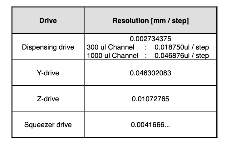
step resolution from PX Pipetting Channel 1000ul.pdf:
…
right, the lld is done on the channel which is controlled by a separate chip from the x-drive. I think this would require [sending a command to the x-drive, requesting the lld status of the channel]^n.
![]() sweat_smile: quote=“rickwierenga, post:29, topic:3056”]
sweat_smile: quote=“rickwierenga, post:29, topic:3056”]
I found it exceedingly helpful to be able to run a script after I make a change to the PLR labware model, and automatically rewrite all definitions. It’d be good to maintain this as long as we can.
[/quote]
Yes, I completely agree. I think this should always be possible: any change we make is rational and has to be applicable for all instances of a Plate/Well/MFXModule/… . It should therefore always be possible to update the script alongside the corresponding item that is updated.
What I meant is: How is dz defining well.get_absolute_location().z, i.e. what is the information chain between the two?
I’d love to generate a flowchart for this but need some help piece together the information.
Thank you, this is very useful! Together with STAR.request_y_pos_channel_n() we should be able to write a nice little function I can imagine to be
  async def probe_y_interval_using_channel(
    self,
    channel_idx: int,
    y_start_location: float,
    y_end_location: float,
    channel_speed: int = 1000,
    channel_acceleration: int = 75,
    detection_edge: int = 10,
    detection_drop: int = 2,
    post_detection_trajectory: Literal[0, 1] = 1,
    post_detection_dist: int = 100,
    move_channels_to_save_pos_before: bool = True,
    move_channels_to_save_pos_after: bool = False
  ) -> float:
Ahhh, this makes a lot of sense: I asked someone from Hamilton before whether their machines can dispense liquid while moving the tip in a spiral … the answer was no because of a hardware constraint, the x-drive and the y-drive & z-drive are controlled by different chips :swe
It should therefore always be possible to update the script alongside the corresponding item that is updated.
one challenge here is having data in a format accessible to the script.
What I meant is: How is
dzdefiningwell.get_absolute_location().z, i.e. what is the information chain between the two?
dz determines the z location of wells, from itemized_resource.py:
def create_equally_spaced(

  items: List[List[T]] = []
  for i in range(num_items_x):
    items.append([])
    for j in range(num_items_y):
      name = f"{klass.__name__.lower()}_{i}_{j}"
      item = klass(
        name=name,
        **kwargs
      )
      item.location=Coordinate(x=dx + i * item_dx, y=dy + (num_items_y-j-1) * item_dy, z=dz)
      items[i].append(item)

  return items
dzdetermines the z location of wells, from itemized_resource.py:def create_equally_spaced( items: List[List[T]] = [] for i in range(num_items_x): items.append([]) for j in range(num_items_y): name = f"{klass.__name__.lower()}_{i}_{j}" item = klass( name=name, **kwargs ) item.location=Coordinate(x=dx + i * item_dx, y=dy + (num_items_y-j-1) * item_dy, z=dz) items[i].append(item) return items
This is it, thank you @rickwierenga!
Looking into this more and more, I am not sure where to make the change to fix the issue of the carrier_skirt messing up the true location of the plate.
Some brainstorming:
We know that this…
item.location=Coordinate(x=dx + i * item_dx, y=dy + (num_items_y-j-1) * item_dy, z=dz)
…is wrong in multiple carrier_site_skirt - dz situations.
But once a Plate has been defined its Wells / children locations are never re-evaluated.
So I can see two options:
- “Representing what is happening in real life”
We correct thedzto its real-world equivalent with is bottom_of_well_to_bottom_of_plate_z_distance orreal_dz+well_z_thickness(I believe this is shorter than “thickness of container base”.
Then we have to
a.) add a condition toassign_child_resourcewhich checks whether the parent is aCarrierSiteand the child is aPlateand
b.) then checks the relationship between carrier_site_skirt_height to the plate’sreal_dzand assigns the Plate.location “sunk” into the carrier_site.
This option does not require any condinuous updating of the Well.bottom location in relationship to the plate’s origin, but instead adjusts the plate’s origin to where it actualy is in real life. - “Only update all wells z location based on skirt_height-
real_dzrelationship”
This is what I tried out over the last week.
But this would require that the condition is also written into theassign_child_resourcemethod but then doesn’t modify the position of the plate but instead modifies the z location of all wells/the plate’s children.
Please let me know what you guys think.
I think the real-world representation option is always the cleanest and most understandable.
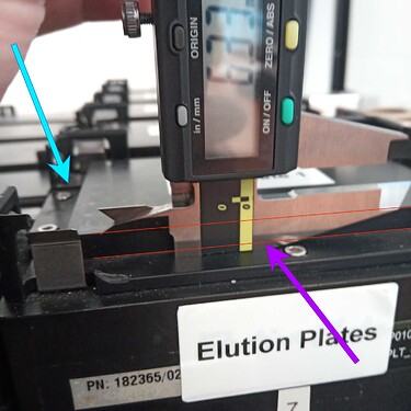
PS. Thinking more about the naming: I don’t remember anymore where the name “skirt” for the elevation inside the site shown here in cyan came from:
But I am currently working on a PlateAdapter implementation for e.g. heater-shaker adapters, ODTCs, and importantly “semi-skirted” and “non-skirted” plates:
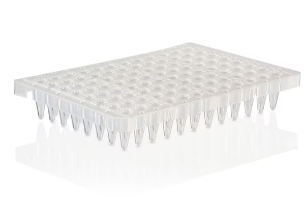
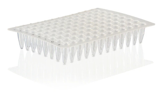
=> Even though PLR does not support these types of labware at the moment (to my knowledge), this means the name “skirted” already has specific meaning in the wetlab.
What do people think about renaming carrier_site “skirt” to “pedestal” in PLR?
Does anyone have other suggestions, or maybe is aware of a standard name of this carrier_site feature (which also appears basically everywhere a plate can be placed, including HHS, HHC, MFXModules, …).
=> Even though PLR does not support these types of labware at the moment (to my knowledge), this means the name “skirted” already has a meaning in the wetlab.
Fun side note:
Only for these semi- and non-skirted plates the current dz == real_dz+well_z_thickness
because real_dz = 0 ![]()
But once a
Platehas been defined itsWells / children locations are never re-evaluated.
This should be the case. The wells do not move around with respect to the plate. (I understand where you’re coming from, I am just naming the design principle I want to use to solve the problem you’re referring to)
We correct the
dzto its real-world equivalent with is bottom_of_well_to_bottom_of_plate_z_distance orreal_dz+well_z_thickness(I believe this is shorter than “thickness of container base”.
agreed, 1 is best.
a.) add a condition to
assign_child_resourcewhich checks whether the parent is aCarrierSiteand the child is aPlateand
this should be in assign_child_resource or CarrierSite or PlateAdapater imo.
=> Even though PLR does not support these types of labware at the moment (to my knowledge), this means the name “skirted” already has specific meaning in the wetlab.
What do people think about renaming carrier_site “skirt” to “pedestal” in PLR?
great observation and thanks for sharing. Let’s do that. “pedestal” (a new word for me :)) is really good.
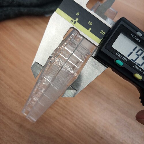
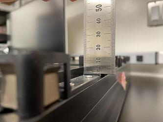
Hey guys, I came here from PR #187, so I limited myself to the overview @CamilloMoschner provided there. I agree this is a super important issue and has caused me tons of problems (namely: z issues in finding well bottom of wells in the same plate, but on different carriers. At some point, we should have a manual with pictures that explain how to measure every kwarg for the Plate and Carrier objects. For the skirt issue, I think the following would be efficient (minimum measurements, minimum code changes needed):
- Measure
total_plate_z(from skirt bottom or well bottom, whatever is lowest):
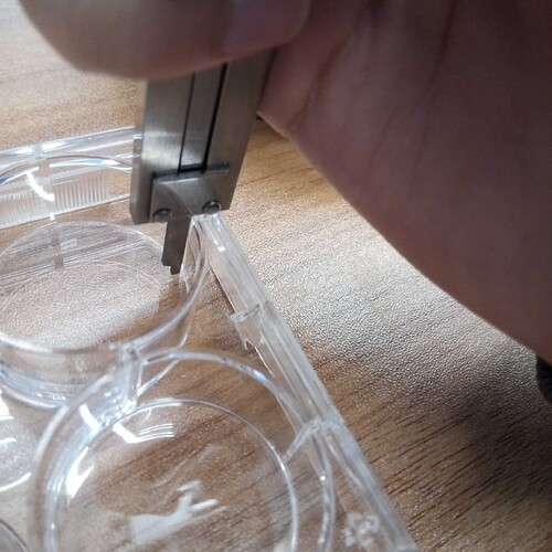
- Measure
inner_well_z, from the top of the plate:
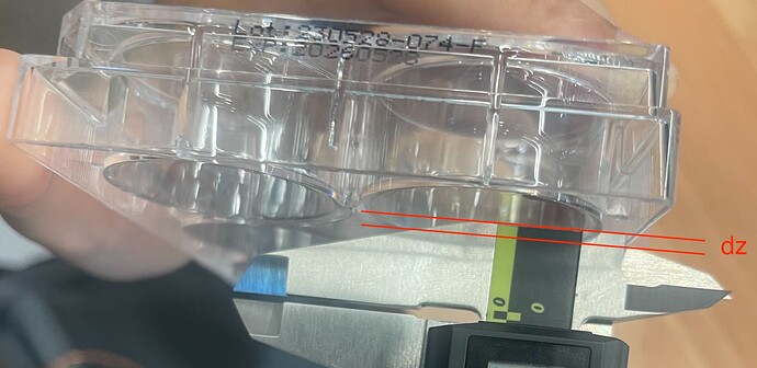
- Measure
skirt_outer_well_bottom_dzas such:
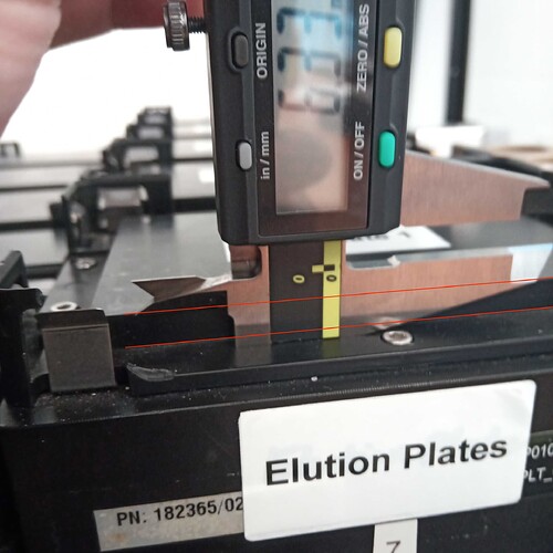
The angle is a bit deceptive, but this measures the difference between the lowest z of the skirt and the lowest z of the outer well bottom (which will rest on a pedestal, if the skirt does not overmatch the pedestal) quite accurately. On skirtless plates, this measurement would be 0, but I would not recommend anyone to use skirtless plates as is on a carrier - rather you should put these on adapters like these:
With these, the thickness of the well’s bottom can be calculated:
well_bottom_dz = total_plate_z - inner_well_z - skirt_outer_wellbottom_dz.
If the well bottom rests on the PlateCarrierSite pedestal, then we can simply add well_bottom_dz to the top of the pedestal to find the well origin. It appears this is precisely what @CamilloMoschner described above:
Hi everyone,
There have been other priorities for a while but let’s fix the PLR labware definitions!
Short summary of the problem discussed above
- Measure
pedestal_dzas such: and compare withskirt_outer_wellbottom_dz. - Measure the carrier’s
pedestal_zby probing with hamilton tip. Yes, this is not a sum of measurements or technical definition, because in my experience, there is a lot of variation between different positions. If you put the same plate on the 5 sites of a carrier, thezlocations of the same well on the 5 different sites is going to vary by about a a mm each. This is simply because of tightening of screws or fitting of the carrier on the deck. Even the same carrier on a different STAR can have a z-difference of 0.5 mm. This also depends on the calibration of the tips, which can independently be tweaked in z position. In a 6-well plate, 1 mm if column height = 1 mL of volume difference! I see no way to get this accurate beyond empirical measurements for each carrier.
I think that with these 5 measurements, the z coordinate of well bottom should be findable by the STAR.
phenomenal documentation
Thank you @fderop for your message and report of the issue’s you’re encountering.
I agree this is a super important issue and has caused me tons of problems (namely: z issues in finding well bottom of wells in the same plate, but on different carriers.
That is exactly the same issue I encountered, starting this thread ![]()
I have been working on identifying the problem and fixing it since February; it would be awesome to have another person working on this!
A couple of things to note and a summary of the work I’ve done so far with @rickwierenga:
- We renamed what has been named “CarrierSite skirt” to “pedestal” because
Plates have skirts,CarrierSites don’t. Small item but the nomenclature can become very confusing.
At some point, we should have a manual with pictures that explain how to measure every kwarg for the
PlateandCarrierobjects.
- I completely agree; this issue is so deeply engrained in PLR and affects so much functionality, making it very complex. A good guide is needed. I’ve created a series of visualisations in the PRs I created for this purpose. But ultimately I aimed to write up a “Plate Definition Post-Mortem” similar to the 50ul Tip Troubleshooting Report / Post-Mortem I wrote after we fixed the 50ul tip definition
Measure
total_plate_z(from skirt bottom or well bottom, whatever is lowest):
- This is already the definition of
Plate.size_z(to my knowledge).
Measure
inner_well_z, from the top of the plate:
- This is already the definition of
Well.size_z-Well.material_z_thickness.
Measure
skirt_outer_well_bottom_dzas such:
- This has been one of the cruxes of the definition problem:
This attribute has so far been completely missing in PLR, and what makes the matter more confusing, this attribute is supposed to be calledWell.dzas it is the offset of the well in relationship to its plate.
However, the termdzhas already been incorrectly occupied in PLR, as theWell.material_z_thickness(due to an import error from VENUS definitions).
Fixing the definition ofPlateis a precedence constraint to fixing the placement issue.
We therefore agreed upon a new definition scheme that I made this visualisation for:
but I would not recommend anyone to use skirtless plates as is on a carrier - rather you should put these on adapters like these
- I completely agree; though most people I’ve met use a metal plate adapter instead of this plastic one because the plastic one tends to create a friction fit between the plastic_adapter and the plastic semi-/non-skirted plate. As a result the robot is at risk of picking up both plastic_adapter+non-skirted plate when trying to move the plate.
Since we didn’t have a plate adapter definition that correctly, automatically adjusts the placement of a plate onto an adapter I developed one viaPlateAdapterin PR#152.
With these, the thickness of the well’s bottom can be calculated:
well_bottom_dz = total_plate_z - inner_well_z - skirt_outer_wellbottom_dz.
- Unfortunately, that is not completely accurate for all plates:
Many plates’ wells actually stick out of the plate top plateau (hence why I added a plate like this in the figure I made above).
This means it is very hard to calculate theWell.material_z_thickness, the attribute you calledwell_bottom_dz, from other information and that is currently being added to allContainerin PR#183.
Instead it is a lot easier to measure it directly on a Hamilton machine:
i. Use the CMM cLLD function that I developed in PR#69,STAR.probe_z_height_using_channel()to measure the pedestal z-coordinate of aPlateCarrierSitewith a pedestal.
ii. Place plate on thatPlateCarrierSite
iii. move channel with tip to the inside bottom of a well of that plate, incrementally decreasing the z-coordinate of the tip, checking whether the tip can scratch the bottom already (not pressing against it), note the z-coordinate
iv. the difference between these two measures is theWell.material_z_thickness
(funnily that is exactly the same way that I’ve seen Hamilton engineers identify this attribute, which they call “thickness_of_container_base”)
If the well bottom rests on the
PlateCarrierSitepedestal, then we can simply addwell_bottom_dzto the top of the pedestal to find the well origin. It appears this is precisely what @CamilloMoschner described above:
- Unfortunately, no, this is not quite what I was trying to say (and I apologise for the confusion, there are multiple parallel problems that all need to be solved at the same time, and I might have not conveyed them all in an easy to understand matter):
What you are suggesting, i.e. adding theWell.material_z_thickness(yourmaterial_bottom_dz) as the offset when a plate sits on aPlateCarrierSitewith a pedestal, is exactly what PLR is doing right now.
→ The problem is that PLR doesn’t change this when the plate sits on aPlateCarrierSitewithout a pedestal AND that PLR currently cannot do so because it misses the definition ofWell.dzandWell.material_z_thickness.
.
I investigated a couple of different methods to fix this:
A.) change the z-origin of the well based on the type ofPlateCarrierSite→ this doesn’t work because the well origin never changes its location in relationship to the origin of the plate.
From a coding side, this is because the well origin coordinates are created bycreate_equally_spaced_2dinpylabrobot/resources/utils.pybut, importantly, thedx,dy, anddzvariables are not attributes ofPlate, making their modifications based on whatPlateCarrierSitethe plate sits on (i.e. with vs without a pedestal) very hard. It would get us back into “offset land” where we have to correct for definition errors with offsets which have to be maintained and updated every time we change the definition, creating infinite technical dept.
From a physical reality side, this doesn’t make sense because it is not the well that changes its location, it is the entire plate.
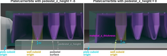
B.) Correct the definition ofPlate→ minimal required information is- getting the site ready:
PlateCarrierSite.pedestal_z_height(added in PR#143) - getting the plate ready:
Well.material_z_thickness(currently being added in PR#183)
Well.dz(currently being discussed to be added in PR#183 under the synonymskirt_base_to_well_base→ reason:dzis wrongly pre-occupied with the value of the realWell.material_z_thicknessat the moment, and we have to transition to the corrected nomenclature without breaking anything)
- getting the site ready:
-
With this information we can simply say:
- If
PlateCarrierSite.pedestal_z_height>Plate’sWell.dz“sink” plate into thePlateCarrierSite(to get the plate origin into its real location) - Else place
Plateorigin ontoPlateCarrierSiteorigin
- If
-
I hope this explains it a little bit better, and showcases how deeply the problem is engrained, and what we have to do to fix it.

Measure
pedestal_dzas such
-
There are two issues with this:
i. The bottom of the pedestal is not at the purple arrow but is higher up (in z-dimension) at the cyan arrow. This little protrusion at the sides is what a plate skirt would sit on top of if theWell.dz>PlateCarrierSite.pedestal_z_height.
@rickwierenga add a new photo to demonstrate what has to be measured to Docs: Plate Carriers
ii. the origin of the
PlateCarrierSiteis at the topmost surface of the site, i.e. the top of the pedestal (this is how VENUS appears to handle this problem, and we chose to adapt a similar solution).
ThereforePlateCarrierSite.pedestal_z_heightis actually a negative float that showcases how far a plate can sink into its site.
there is a lot of variation between different positions. If you put the same plate on the 5 sites of a carrier, the
zlocations of the same well on the 5 different sites is going to vary by about a a mm each. This is simply because of tightening of screws or fitting of the carrier on the deck. Even the same carrier on a different STAR can have a z-difference of 0.5 mm. This also depends on the calibration of the tips, which can independently be tweaked in z position. In a 6-well plate, 1 mm if column height = 1 mL of volume difference! I see no way to get this accurate beyond empirical measurements for each carrier.
- Yes, that is a big problem for using robots for actual experiments, and I believe this is one of the main reasons why most robotics in biology has been confined to what I call “process churning”, i.e. perform the same repetitive tasks over and over again, not changing anything about the setup… because as you said: even changing a plate to a different
PlateCarrierSiteon the same carrier can have different offsets.
What we all seem to want though is using robotics for experiments, i.e. tasks that are fundamentally changing from one automation run to the next. (thanks to procedural robotic control like PLR this is now possible from a software side but the hardware is now the next challenge).
I found working with careful considerations of tolerances gets me 90% where I need to go.
Plus, for those really tough applications there is lld_mode=4, z-touchoff, i.e. crash tip into the bottom and aspirate from there… but that might not work for all applications and it is slower.
Besides that I am myself trying to work out a couple of new solutions for applications where this has become a limiting problem
thank you everyone for the detailed reporting & fixing of this important issue. I was more venus-pilled than I realized, but I’m happy that we’re working on fixing this.
some point, we should have a manual with pictures that explain how to measure every kwarg for the
PlateandCarrierobjects
a WIP! See: Plates — PyLabRobot documentation and Plate Carriers — PyLabRobot documentation.
Can I put your pictures on the docs website?
If you put the same plate on the 5 sites of a carrier, the
zlocations of the same well on the 5 different sites is going to vary by about a a mm each. This is simply because of tightening of screws or fitting of the carrier on the deck.
This is really unfortunate, but Camillo also experiences this. He mentioned we probably need to move away from “clamp-carriers”. In the meantime, I think custom definitions for each physical resource in a lab that apply ad-hoc offsets to the PlateCarrierSites is probably the best way forward for these hardware inconsistencies. (def MySpecificCarrier -> PlateCarrier)
- This is already the definition of
Plate.size_z(to my knowledge).
correct
I investigated a couple of different methods to fix this:
8B is definitely what we should do.
@rickwierenga add a new photo to demonstrate what has to be measured to Docs: Plate Carriers
is this current image not the topmost item below the pedestal?
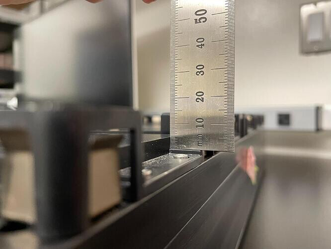
- Therefore
PlateCarrierSite.pedestal_z_heightis actually a negative float that showcases how far a plate can sink into its site.
![]()
is this current image not the topmost item below the pedestal?
Apologies, this was not meant to be a question or an imperative… I mistyped and it should be “added”, i.e. pointing that you already added this correct photo for the measurement ![]()
