How can a report be generated to evaluate the success or failure of aspiration operations following a cherry-picking process using Beckman Conductive (LLS) tips? This report should summarize which wells were successful in aspiration and which ones failed
1 Like
Hi Kabha,
There’s a few ways to go about this, and it would be helpful if you could provide an overview of your LLS settings to move forward.
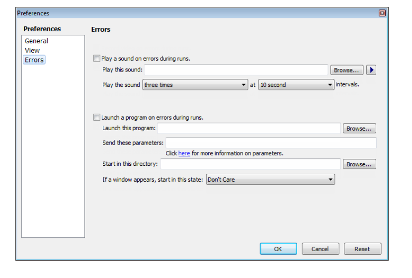
In most scenarios I would recommend making an external program to do this. The simplest of which would be a program that executes when an error is activated. If you also execute a “create report” type program that makes an excel file with the given output information, you could edit it with a program that executes upon error detection. You can run .exe files upon errors, and if you specify to pull info from LLS errors, you can have your program define “success” or “failure” of an aspiration for your custom report.
You also have the option of doing something like this from the Span-8 pipetting or error files, as they are generated every run.
The last option would be to do work with the data-set reporting feature. This might be the best option for you if you aren’t trying to use any outside programs, but it will limit the amount of customization you would have in your reporting output.
I’m unsure if this will update live with success or failure of the LLS system in real time as I cannot test this on an actual instrument.
PLEASE DO EXTENSIVE TESTING TO VERIFY THIS OUTPUTS CORRECTLY USING AN INSTRUMENT WITH LLS ERROR HANDLING EVENTS BEFORE PROGRESSING ANY FURTHER IN YOUR METHOD DEVELOPMENT & METHOD IMPLEMENTATION.
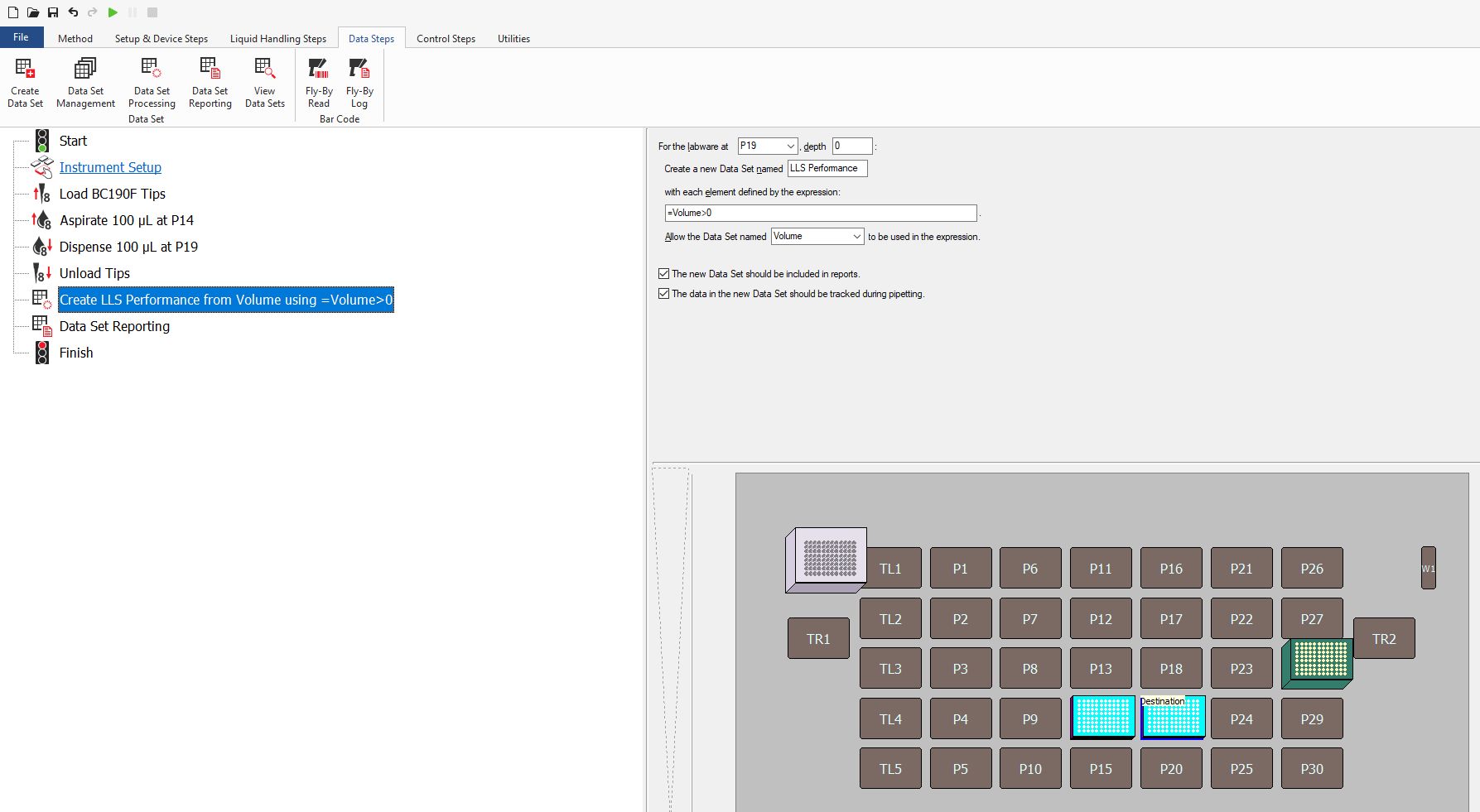
What you’ll want to do is at the end of your method, add a “Data Set Processing step”. For your destination labware, create a new dataset with a specific name. Enter the expression =Volume>0. Allow the dataset named “Volume” to be used the expression and ensure both boxes below that are checked off.
The expression =Volume>0 basically creates a boolean dataset that will output TRUE if there is volume in the destination, or FALSE if the destination volume is 0. The next step now is to export that dataset for your report.
After that, add a Data Set reporting step as the last step in your method. Choose a filepath for your destination.
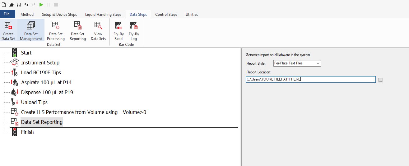
You’ll still have to do some trial and error about what output type you want, and you’ll have to deal with not being able to configure the naming convention of the reports themselves, as you can really only export ALL datasets of all labware.
Let me know how it goes, and again, please test heavily if you decide to go with the data-set option. Good luck!
Doug
Hey Gobron,
I recently completed an external program successfully. Thank you.
However, I would like to know your recommendations for using the Technique Browser settings. I am facing an issue where there is RNA (liquid type) in the PCR plate, but sometimes the system fails even though there is enough volume. For example, with 10µl per well on the PCR plate, when aspirating 2µl from the same well, an error occurs indicating no liquid is present.
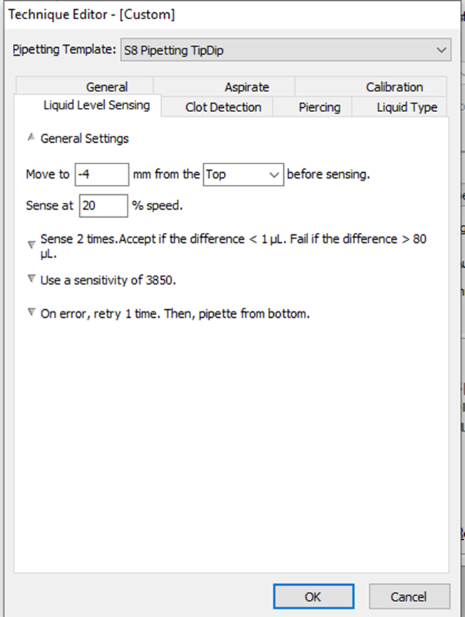
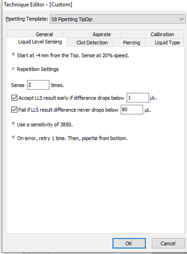
I have attached a picture of our liquid level sensing settings. Please let me know your recommendations.
Hi Kabha,
Glad to hear you were able to make your own program. As for your current issue, LLS is very sensitive for a number of factors. I would need a few pieces of information before I would be able to identify the exact cause of your issue:
- At what point is this Liquid Level Sensing taking place in this method?
- Has the well been access by a tip before in this method?
- Have the exact tips used to perform the LLS done any liquid handling prior to this step?
- What tip type are you using for this step?
- What is the approximate viscosity of your material? (I usually equate this to what % glycerol/water solution is this most similar to. Most people don’t have access to an actual viscometer so eyeballing similarities to % glycerol is completely fine for this approximation.)
- What is the size of your plate well & what % of the well volume does the 10uL of material take up?
- Are the source volumes of each of the wells in the plate expected to be a constant 10uL for each transfer?
- At 10uL of source material in the well, how much distance (in mm) are there between the top of the liquid in the well and the bottom surface of the well?
- What is the plate labware type the aspiration step is taking place in?
- Is a blowout air gap absolutely needed for this step?
I try to avoid extremely low volume LLS if possible, specifically due to its unreliability. However, I do believe it is possible. If you could answer as many of these as you can I could probably point you in the right direction at the very least.
Best,
Doug
Hey Gobron,
Thank you.
About your questions:
1. At what point is this Liquid Level Sensing taking place in this method? It occurs during the cDNA process, specifically at the first step where RNA is taken for the PCR Plate (Eppendorf twin.tec® Real-Time PCR Plates 96).
2. Has the well been access by a tip before in this method? : No.
3. Have the exact tips used to perform the LLS done any liquid handling prior to this step? : No.
4. What tip type are you using for this step? : BC50F_LLS.
5. What is the approximate viscosity of your material? (I usually equate this to what % glycerol/water solution is this most similar to. Most people don’t have access to an actual viscometer so eyeballing similarities to % glycerol is completely fine for this approximation.) : Water (RNA)
6. What is the size of your plate well & what % of the well volume does the 10uL of material take up? 1. The size is 250 µL; it will occupy 4% of the well volume.
7. Are the source volumes of each of the wells in the plate expected to be a constant 10uL for each transfer? : 1. No, it ranges between 2 µL to 10 µL.
8. At 10uL of source material in the well, how much distance (in mm) are there between the top of the liquid in the well and the bottom surface of the well? : 1.2 mm.
9. What is the plate labware type the aspiration step is taking place in? : 1. It’s this one: Eppendorf twin.tec PCR Plates LoBind.
10. Is a blowout air gap absolutely needed for this step? : 1. Yes, to ensure that the entire volume is dispensed.
1 Like
Hi Kabha,
Thanks for providing the answers to my questions. It seems like you’re already doing most of the things I would suggest, and are working with material that is relatively successful with LLS functionality (Water). That being said, I would try the following things:
-
In your Technique, set:
Liquid Level Sensing → General Settings → Move to 4mm from the BOTTOM of the well before sensing. Sense at 10% speed.
LLS works on capacitance, and that can be affected as you go lower into the well. As the well narrows, that capacitance of the air within the well can change from the baseline that the Biomek establishes when sensing begins closer to the top of the well. In your current instance this is -4mm from the top. By starting sensing significantly lower in the well, your sensing baseline will be that of the increased value before coming into contact with the liquid. -
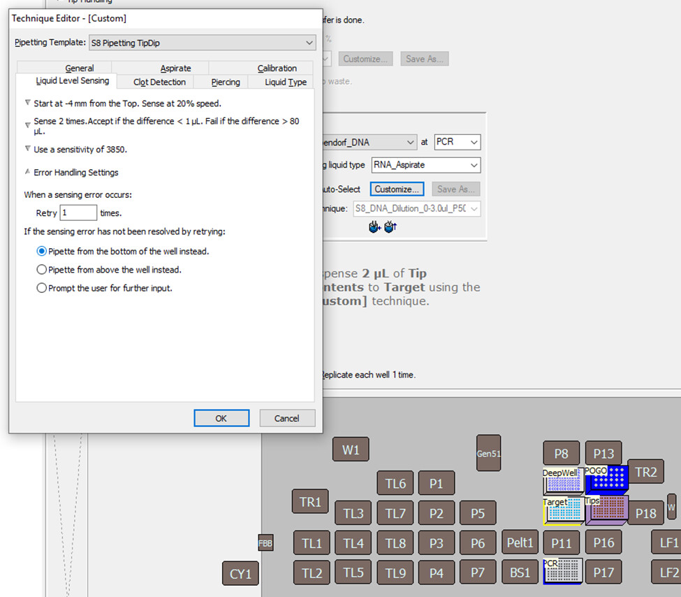
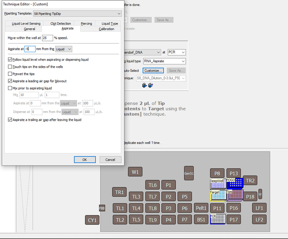
Again in your technique editor, set:
Aspirate → Aspirate at -1mm from the Liquid.
As of now you’re aspirating -5 mm from the top of the liquid, which is a greater distance from the top of the liquid to the bottom of the well. There shouldn’t be too much problem with this, but it might affect your pipetting accuracy if there is too much pressure exerted on the tip if the Span-8 probe is trying to force the tip below the bottom of the well, especially as you have already selected the setting to have the probe follow the liquid down during aspiration. -
In:
Instrument Setup → Select the labware (the labware being used in this aspirate step) Labware Properties → Select: Sense the liquid every time a well is accessed “From the Liquid.”
This will ensure there are no skipped wells if the system already believes it knows the well volume. In many cases, especially when multiple aspirations from the same source have taken place, or dispenses have taken place, the Biomek will assume it already knows the volume of the well and avoid doing LLS again. This setting tells the Biomek to sense in the well every time it accesses its contents. In the same Labware Properties page, ensure that:
Labware Contains UNKNOWN Volume.
Using “Known” volume will disable LLS, and using “Nominal” will assume the value entered into the labware, but will do LLS as well. In my opinion, “Nominal” leaves too many areas for potential errors in the programs logic, so “Unknown” will always be the optimal choice. -
In your transfer step, ensure that all your aspiration steps are being done “From the Liquid” and that the technique is dictating what the aspiration location conditions are. If your step says: “[Overrides Technique]”, your LLS settings may not apply.
These changes will most likely take some calibration, especially the “Start Sensing at” height listed I described in item 1. Let me know how it goes, and if you have any further questions. Good luck!
Best,
Doug
1 Like
Thank you.
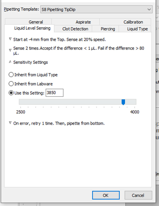
Regarding the sensitivity settings:
From which number should we start the calibration? If it’s not good, should we increase it?
What is the range for the sensitivity number you recommend, both minimum and maximum?
Hi Kabha,
Apologies for not replying to you sooner.
Long story short, I would start with the sensitivity setting used in the “water” liquid class definition. I belive that value is 2500, but I could be wrong. Check to ensure you have that value set in your technique before you begin.
I would also say that incremental increasing of your sensitivity value if your first pass is not working is, what I would consider, the optimal way to calibrate your LLS settings.
Generally, aqueous + polar liquids (water) will have a lower LLS sensitivity requirement as the tip capacitance will change more drastically when contact is made. More viscous + non-polar liquids (glycerol) will require a higher sensitivity.
In your circumstance, because the distance down to the liquid within the well is greater than average, you have a higher likelihood of preemptively setting off the LLS detection early. Setting the LLS value low initially will help you avoid this error, which will not even give you a error message, but will just aspirate air and you’ll never know. But, as always, you won’t really know how the method works until you test it with your specific use-case conditions.
Were you able to make any progress on calibrating your LLS settings? If so how did it go? Please keep me updated and if I can help any further.
Best,
Doug
Hey,
I have tried many options but keep facing an issue with false negative results. The system indicates there’s no liquid, even though there is.
I have tried adjusting the sensitivity settings between 2800 and 3800. The volume on the labware is inconsistent, ranging from 8-15 µl, and I need to aspirate between 2-4 µl.
Could you please send me the template and technical details you use for conductive tips? I’m getting too many false negatives and I’m not sure what the issue is.
Hi Kabha,
Sorry to hear that it hasn’t worked out. Unfortunately, I do not have access to a Biomek at this time, and I don’t have a working method/technique I could send you. I pulled the information from the manual and some searching in my virtual instance of the Biomek5 software.
I’m assuming you tried a number of the items I listed above. Did you change the height at which it begins sensing as I listed in item 1 of my suggestions comment? Adjusting at when your tip begins sensing is where I would guess you would be able to see the most improvement in your assay. I’m unsure what else I can suggest to you moving forward other than that.
Apologies for not being more help, please let me know how it goes!
Doug