Tip Scanning with Autoloader

Hi!

I think I’m very close to having this working but I keep getting an error. This entire carrier is 300uL tips, want to verify that they are 300uL at the beginning of the script. It is already loading/unloading at the correct time and the Autoloader is scanning but I keep getting this error. Where is my mistake? Thank you!


Hello,

I can assist with this. But would you be able to give me a bit more detail and perhaps a trace log? Is this on a Vantage or a STAR? And if it is on a STAR, is your STAR equipped with a 1D or 2D autoload?

Matt

Thank you! Hamilton Star, 2D Autoloader

I can send the trace information in the morning, the error in the trace file was very vague

Here is the trace file showing the error that occurs after the Autoloader attempts to scan the tip racks

Since you are using the new 2D autoloader have you tried adding the specific ROI and illumination labware properties to each of your carriers? You can find them in the Venus 6 programmer’s manual or from the guide in the following link: 2D AL properties_VENUS 6-2 Software Programmer's Manual_en.pdf :: Hamilton

image

Each carrier on your deck layout may end up with 5 additional labware properties, otherwise the defaults for these parameters are applied instead and they may be inaccurate.

My apologies, I just realized I typoed - we have a 1D Autoloader, and are using Venus 4.

Hi,

My apologies for the delay but the 1D autoload makes all the difference. With the MFX tip isolator modules the barcode on a tip rack is roughly an additional 10mm higher in the z than on other standard tip carriers. This means that when the 1D scanner rotates to read horizontally the laser will not be in line with the barcodes. So these barcodes cannot be read without a 2D Autoload or Cognex attachment. See the image below:

No worries! Thank you very much for the response. I have the same settings in place for tip carriers of the standard height in your photo (to the right/forefront) that are yielding the same error when I go to try to scan them. The settings I am trying to use for those are exactly as I included in the screenshots as well. What detail am I missing to get this working with the standard height tip carriers?

Hi @Ham ,

Can you include a picture of your tips loaded in the tip carrier? With the settings listed, there should not be an issue. Just want to confirm there isn’t something else that is affecting the barcode scan.

Hi, I know it has been almost a year since this was posted, but you might be able to help me.
Using the guide you provided, I am trying to set the ROI to be close to the bottom of the labware, but have had no luck on getting the barcode labels to read.
We are using MFX carriers with deepwell plates. Any help would be greatly appreciated.

1 Like

Hi @serg,

Are you using a 1D or a 2D autoload? And are you using a VANTAGE or STAR? While deepwell plates on an MFX carrier sound like they would not be a problem, there are just so many vairables to consider. So along with the aforementioned questions, what kind of barcode are you using (an example picture would help me immensely!)?

Matt

Hi @MatthewSmith_Hamilton we have a 2D autoload on a STARlet.


We have been able to scan the barcode when placing the barcode about one label height higher, but it has not been consistent.
we have been able to scan taller barcodes placed at the bottom like in the picture.

these are the properties we are using. we have been tinkering with the reader illumination setting so please ignore that one. the most up to date value we are using is “2;2;2;2;2;10;400”

All good, ended up being the cognex scanner being too high, causing the viewfinder to be too high to scan the desired height.

Hi @serg,

Here is a section from the Venus 6 programmer’s manual:


I have found that the optimal settings for MlStar2DReaderIlluminationSettings have been more around “2;1;2;1;1;3;200”. I think your settings may be adding too much light into the camera and a gain of 10 is likely to blur and distort the black bars of the barcode.

A Y center offset of 20 means it will push the ROI 2mm to the right from the horizontal center. From there, the Y width of 860 means your ROI will be 86mm wide, or that the left and right boundaries of the ROI will be plus and minus 43mm from that 2mm offset from the horizontal center. But your Z center offset isn’t an offset from the center of the scanning window like the Y offset is. It’s an offset from the origin of the system, 100mm below deck. So a Z center offset of 45 is still technically putting the ROI under the baseplate of the system. This value should be more on the order of 2000 or somewhere around there: Take a look at the example below:


The bottom of the carrier is already at 100mm and then about 91mm is measured to the center of the barcode. This would give me a Z center offset of about 191mm or a value of 1910 in the labware properties.

Try these out and let me know how it goes.

Matt

3 Likes

Hi @MatthewSmith_Hamilton

I got onto this post because I have some issues with the 2D barcode reading on a STAR-V in Venus 6.3.2

Previously I would use a modified library to create a firmware command. Basically the same Hamilton used in the past for VoV. It calculates the ma parameter (ROI)

So back then I had no issue in reading any barcode. The issue back then was just having to deal with all the possible errors that could happen. So when 6.3.2 came out and I could scan barcodes, I reverted back to this. However I have two carriers that pose an issue for me

Basically it is the carrier for the Hamilton Cooling Carrier (32 positions, you know the one with 32 individual .rck files that all needs teaching :wink: ) and the MFX carrier where the QcG is parked. Both suggest me to have a WOI setup

Knowing that my manual firmware command driven method worked for reading any barcode, means that if I setup this ROI, I should be “into the money”

Just to clearify

If I calculate my firmware command to be : ma -327 1565 599 350 ( < ∆Yw > <∆Zw>) how would this translate to the correct setting in the single step loading. In this dialog you can set those 4 options too. Would it be in mm and thus be -32.7 156.5 59.9 35.0 or what would it be?

Thanks for helping out!

2 Likes

Hi @Pascal,

While the STAR line’s 2D autoload and the VANTAGE line’s IDL are meant to serve the same functions (unload/load carriers and read barcodes) there are an increasing number of features that you would notice are different between the two as you move from loading with a command at face value into the firmware commands behind the scenes. It starts with the STAR using labware properties on the deck layout at minimum to specify your ROI while the VANTAGE has all the ROI (WOI on VANTAGE) information in the advanced tab of the loading command. And then in firmware commands both STAR and VANTAGE utilize the ma parameter for defining the ROI/WOI but the individual ma parameters have different meanings:

STAR:

  1. First number: Y origin (deviation from center in 10ths of mm)
  2. Second number: Z origin (deviation from bottom of ROI in 10ths of mm)
  3. Third number: Y width (entire width of ROI in 10ths of mm)
  4. Fourth number: Z height (entire height of ROI in 10ths of mm)
    Both the first number and second number point to the center of the ROI. The second number, Z origin, is the position from the system origin 100mm below the deck. Hence why it should have values starting at at least 1000.

VANTAGE:

  1. First number: Left most position of WOI in 10ths of mm
  2. Second number: Bottom most position of WOI in 10ths of mm
  3. Third number: Y width (entire width of WOI in 10ths of mm)
  4. Fourth number: Z height (entire height of WOI in 10ths of mm)
    Both the first number and second number point to the bottom left corner of the WOI. The second number, Z origin, is the position from the system origin 100mm below the deck. Hence why it should have values starting at at least 1000.

Then the parameters further differ for VANTAGE when you are looking at the advanced tab in the load command:

  1. W: Y width (entire width of WOI in mm)
  2. H: Z height (entire height of WOI in mm)
  3. Z: Distance from the bottom of the WOI to the deck in mm
  4. Y: Distance from Y origin (position where camera will take a picture) to left edge of WOI in mm
    The advanced tab does not consider the system origin for the WOI and your Y (fourth) value is often just your W (first) value multiplied by -0.5. Also take into consideration how the order of these four numbers is different between the VANTAGE firmware command and the advanced tab listing.

So let’s look at your parameters for ma: -327 1565 599 350. Assuming this is the order they are in for ma, if you were to put these in the advanced tab I would put them as: 59.9 35.0 56.5 -32.7. This would be a WOI that is 59.9mm wide, 35mm tall, starts vertically 56.5mm from the deck, and starts horizontally 32.7mm from the center.

Matt

4 Likes

Hi @MatthewSmith_Hamilton

Thanks for the great explanation, I simply can’t get that to work. Here is my train of thought.

I use a library that utilizes some features from the Labware Property Query to obtain my measurements. So when I am looking into the firmware guide to calculate the ma (which worked for the firmware command driven reading) I get the following results for my MFX carrier with the QcG, 4* 20ml troughs and 4 tip sites

YW0 = -424
ZW : 2147 (Rackbase is 214.7)
YDW : 826 (82.6 is the Y-distance from the labware)
ZDW : (Labware Height = 234,7) : 2347

The ma command would then look like ma -424 2141 826 2347

Translating that into the loading step would give me in theory a WOI of

W : 83
H : 234
Z : 214
Trigger : -42

However, that results in a not-read of the barcode. So I decided to scan a regular Tip Carrier (Why? because I am scanning the same type of carriers, but now mounted on a base plate) and I look in the HxCom file to see the firmware command, the result : -300 2000 550 350 for the parameter MA.

Which translates into - according to above example - provided :

W : 55
H : 35
Z: 200
Trigger -30

But that won’t let me scan the barcodes. So I play around with the Z and again, it’s not working.

So I am again diving in the help file and here is states that - for tip carriers - the suggestion is to take 70% of the raster (672 in my example) so my values become

W : 67
H : 70
Z : 70
Trigger : -33

Also no luck.

I am getting to a point that I am amazed that a default carrier from the NGS-STARV is not being able to be processed and I have to fiddle about to get to these values. In my mind these default carriers (for a framework) should be supplied then with a documented WOI correct?

Hi Pascal,

@MatthewSmith_Hamilton just tested scanning a carrier using the default carrier definition and default loading step command on a VANTAGE running 6.3.2 and was able to scan barcodes without issue. See this link for the test method.

I recommend using the default settings and commands. If you’re still having issues, then something else is going on and we’d need more materials (method, diagnostics files, etc.). We can follow up offline to troubleshoot and then later update the thread with the fix.

Best regards,

Eric

Hi all,

While this is mostly a review and already highlighted in the VENUS programmer’s manual, I wanted to provide a more detailed overview for correctly utilizing labware properties to scan barcodes.

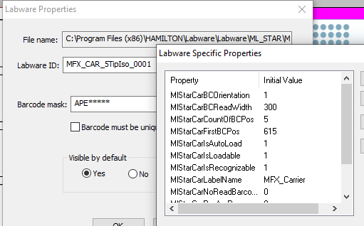
The following table is a list of the general labware properties that are applicable to all of our larger platforms: STARline with a 1D autoload, STARline with a 2D autoload, and VANTAGE with the IDL. While they are pretty self explanatory there are a few key things to point out which are highlighted after the table. There is also a 3rd table near the end of this post that defines two more labware properties, but I specifically singled them out to give a more detailed explanation on their use.

Labware Property Type and Default Value Description
MlStarCarrierBarcodePos Integer (43) The distance in 10ths of mm of the carrier barcode flag from the rear of the carrier
MlStarCarrierBarcodeWidth Integer (85) Width of the carrier barcode flag’s reading window
MlStarBarcodeReadSpeed Integer (1281) The speed that the autoload/IDL loads the carrier
MlStarCarCountOfBCPos Integer The total count of barcodes that will be visible to the autoload/IDL
MlStarCarBCOrientation Integer A value of 0 is used for vertical, 1 for horizontal, and 2 for all directions
MlStarCarFirstBCPos Integer The distance in 10ths of mm of the carrier’s first site barcode from the rear of the carrier
MlStarCarRasterWidth Integer The distance in 10ths of mm between each barcode site
MlStarCarBCReadWidth Integer Width of the carrier site barcode’s reading window
MlStarCarIsRecognizable Integer Whether or not the carrier has a magnet below its barcode flag
MlStarCarIsLoadable Integer Whether or not the carrier is loadable
MlStarCarIsAutoLoad Integer Whether or not the carrier is loadable by the autoload/IDL
MlStarCarPosAreRecognizable Integer A value of 0 means the labware on the carrier cannot be verified by the labware presence sensor and a value of 1 means that the presence sensor will have to detect labware on a given site in order for that labware’s barcode to be read
MlStarCarNoReadBarcode Integer A value of 0 means barcodes can be read and a value of 1 means no barcodes can be read upon loading the carrier
MlStarCarLabelName String The name of the carrier that will be displayed in the event of an error message

The property MlStarCarCountOfBCPos refers to the number of scannable barcode positions on the carrier. I think there is some confusion in regards to thinking that this property refers to the number of sites/containers that exist on the carrier. But say you have two or more sites that are side-by-side on a carrier (like 20/60mL trough sites or adjacent QCGs) - these technically count as a single barcode position since they will pass by the barcode scanner on the autoload/IDL at the same time when the carrier is loaded.

The property MlStarCarPosAreRecognizable slightly differs between the STAR and VANTAGE platforms. Positions being recognizable refers to the use of the labware presence sensor which exists on both platform lines but as different hardware. The presence sensor on a STAR is directly adjacent to the barcode scanner and scans in one location/height for a reflection of its beam on the labware to verify the presence of sample tubes. The presence sensor on the VANTAGE is located behind the power button on the far left of the loading tray and will adjust vertically to the location that rack or tube labware may be. It too scans for a reflection of its beam off the labware in order to verify labware presence. If this labware property is set to a value of 1, labware presence verification precedes the barcode scanning - a barcode at a specific location will only be reported when that barcode’s labware has been verified to be present.

MlStarCarCountOfBCPos, MlStarCarFirstBCPos, and MlStarCarRasterWidth go hand-in-hand for determining scanning positions. MlStarCarCountOfBCPos determines the total number of times to scan for barcodes on a carrier. MlStarCarFirstBCPos is where the first scan will happen. Each next scan is the distance specified by MlStarCarRasterWidth towards the front of the carrier.

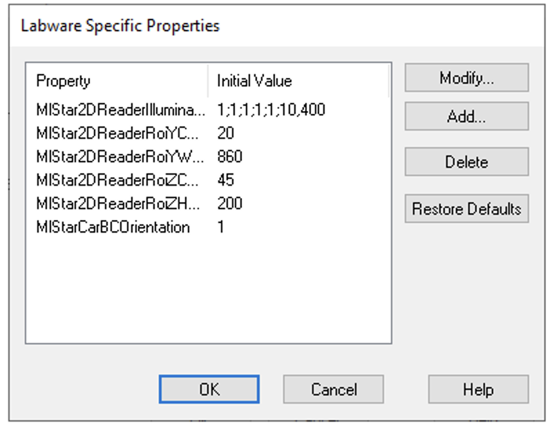
Now if you have a STAR with a 2D autoload, VENUS is capable of handling an additional 6 unique labware properties that can either be applied to individual racks on a carrier or the carrier itself. The following table details those properties:

Labware Property Type and Default Value Description
MlStar2DBarcodeCarFirstBCPosShift Integer (0) The horizontal shift in 10ths of mm for correcting the barcode read position
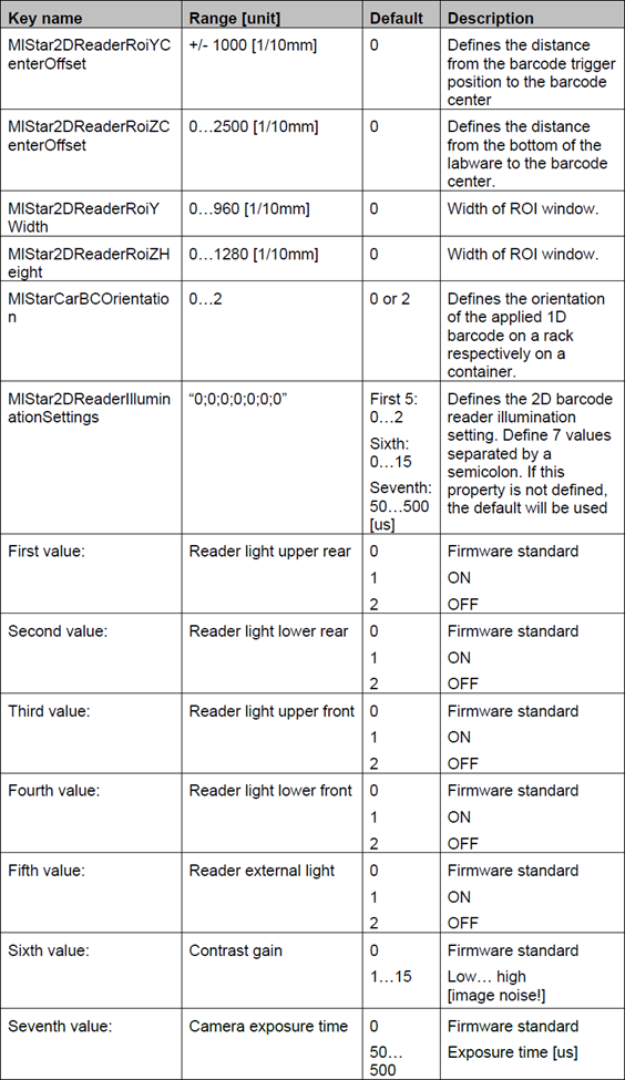
MlStar2DReaderRoiYCenterOffset Integer (0) The horizontal distance in 10ths of mm from the center of the barcode reading window
MlStar2DReaderRoiZCenterOffset Integer The vertical distance in 10ths of mm from the bottom of the labware that has this property to the middle of the barcode
MlStar2DReaderRoiYWidth Integer The width of the barcode reading window
MlStar2DReaderRoiZHeight Integer The height of the barcode reading window
MlStar2DReaderIlluminationSettings String (“0;0;0;0;1;0;0”) The 7 illumination settings for the 2D autoload:

The labware property MlStar2DBarcodeCarFirstBCPosShift should only ever be used to tweak the location and time that the barcode scanner scans a site. Metal, glossy laminates on barcode stickers, and other things can sometimes produce a glare on the camera of the 2D autoload. This property allows you to shift the position of scanning horizontally as a means of attempting to minimize such glare.

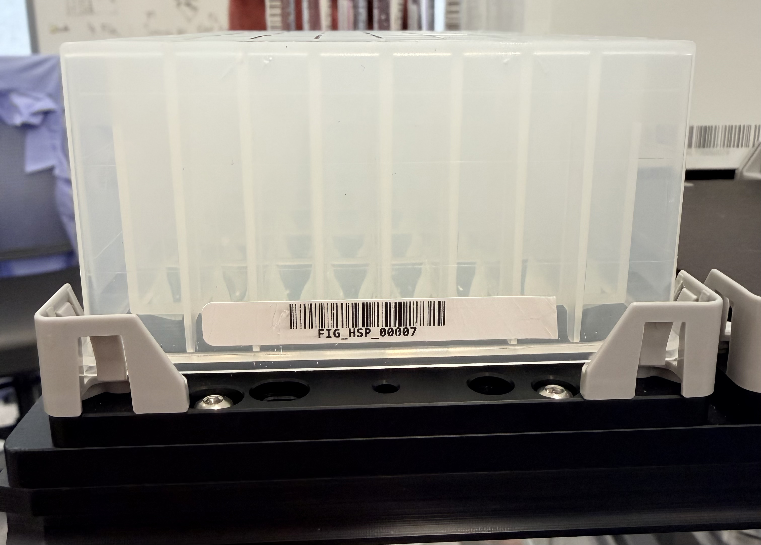
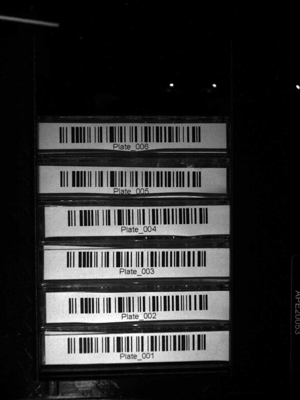
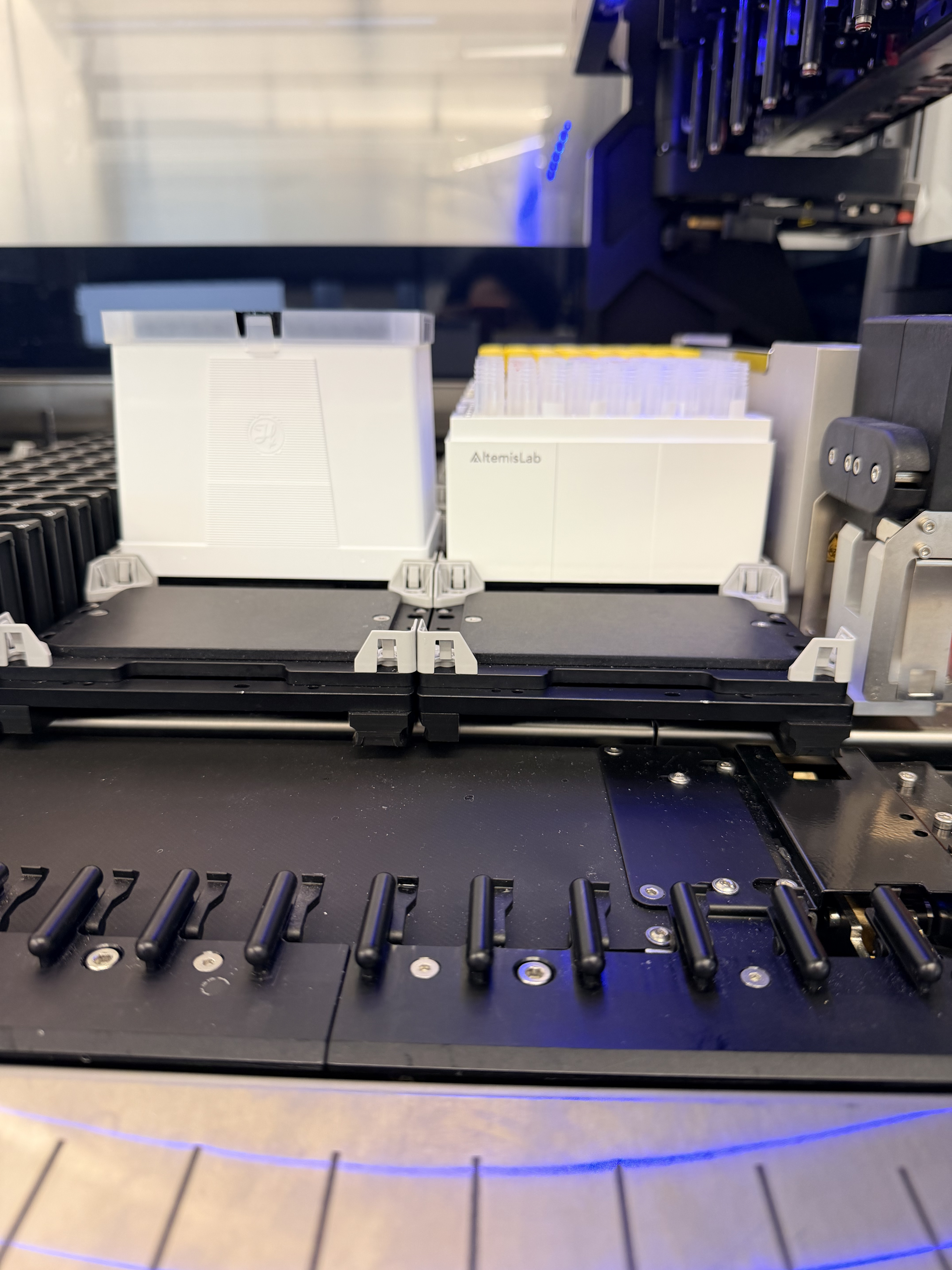
Prior to getting into the four region of interest (ROI) based labware properties, I just wanted to mention that the labware property MlStar2DReaderIlluminationSettings is pretty straightforward - while it is tough to know what to pick for it without seeing how they actually affect the image taken by the Cognex, I don’t think there needs to be much deviation from a setting of “2;1;2;1;1;3;200”. This sets the top two LEDs on the Cognex camera on, the bottom two off, the external blue LED set on, the gain factor of image processing to 3, and exposure time to 200ms. These settings result in image clarity seen in the following image:

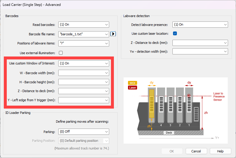
The last four labware properties in the table are what’s used to create the ROI for a given barcode position. Note that the center offsets have different origin points in regards to their origins. The horizontal (Y) origin is dead center to the barcode scanning position with an even distance to the left and the right. The vertical (Z) origin is at the bottom of the labware that the property is applied to - so on a carrier the Z center offset origin is the deck while on a rack the Z center offset origin is the bottom of that rack. So note that you could have a 5-position carrier with a set of ROI labware properties specified on it OR you could have a 5-position carrier with 5 racks snapped to it on the deck layout and each of those racks have their own individual sets of ROI labware properties and optional light settings. The labware property from the first table, MlStarCarBCOrientation, can also be applied to individual racks.

Now here is the kicker - if you were to just add ROI labware properties to each rack snapped on a given template, that isn’t enough to have the load command utilize those properties. This brings us to the following table with two more labware properties to consider:

Labware Property Type and Default Value Description
MlStarReadBarcodeOnPositions String Determines which site positions will be read during a load command where clauses are joined by a semicolon and each clause is “barcode return position = site name”
MlStarCarOpenRasterBarcodePositions String Defines the barcode read positions for an irregular carrier where barcode reading positions are not computed via MlStarCarCountOfBCPos, MlStarCarFirstBCPos, and MlStarCarRasterWidth

If the carrier has no ROI labware properties and instead the snapped-to labware on that carrier has ROI properties, then the carrier MUST have the labware property MlStarCarOpenRasterBarcodePositions specified. This property overrides MlStarCarFirstBCPos and MlStarCarRasterWidth by parsing its string value where that string value should be a list of increasing numbers equal to the number of positions specified by MlStarCarCountOfBCPos. The values of those numbers are the integers in 0.1mm of the positions along the carrier to scan. To assist with understanding this, take a default 5 position carrier: the back/first site is 61.5mm from the rear of the carrier and each subsequent site forward is an additional 96mm - so where MlStarCarCountOfBCPos is 5 your value for MlStarCarOpenRasterBarcodePositions will be “615;1575;2535;3495;4455”. Only with this labware property added to the carrier will a load step respect the labware properties from the second table if they are added to individual racks on the carrier.

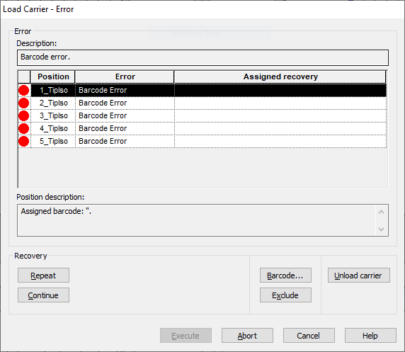
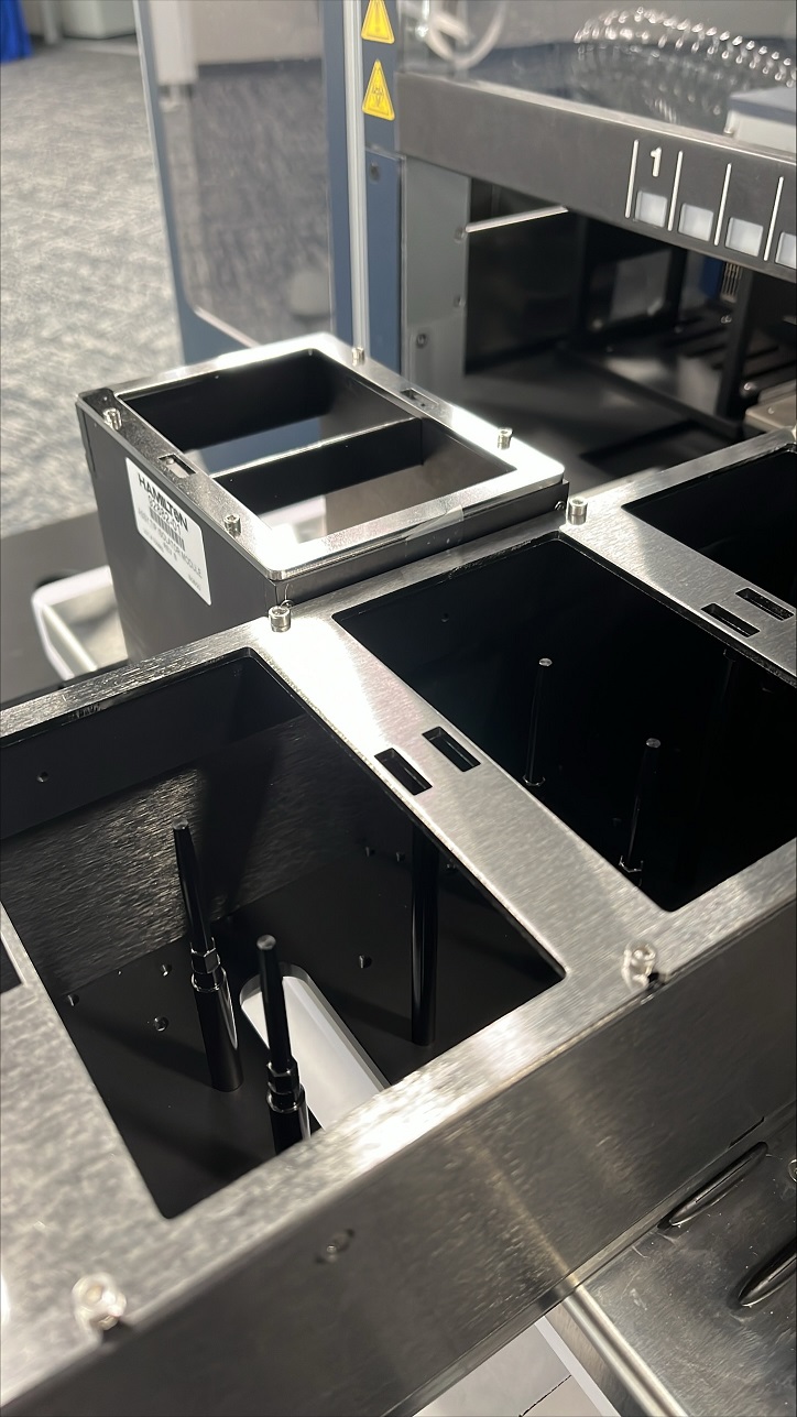
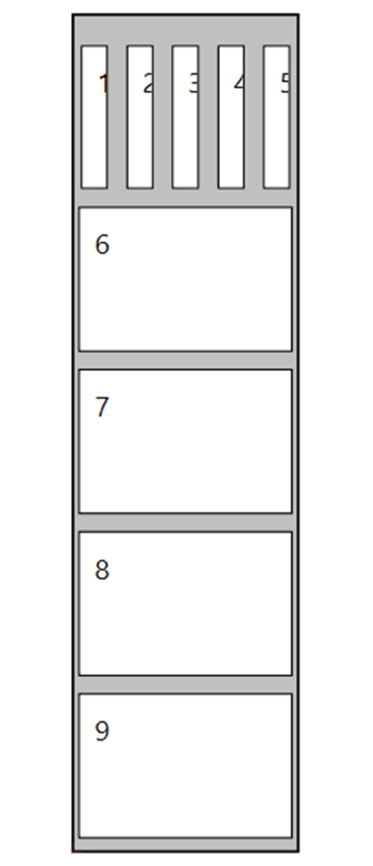
Now one more labware property: MlStarReadBarcodeOnPositions. There is an issue if you have sites side-by-side with each other in which case this labware property is needed. Take the following carrier as an example:

This carrier has 9 sites but only has 5 scannable positions. Its property MlStarCarCountOfBCPos will be 5. If MlStarReadBarcodeOnPositions is left unspecified a load of this carrier will scan possible barcodes on sites 5 through 9 but attempt to assign those barcodes to site names 1 through 5. So we would utilize a string of “1=5;2=6;3=7;4=8;5=9” for MlStarReadBarcodeOnPositions to show that position 1 of the load command needs to return and assign a found barcode to the labware that is snapped to site 5, position 2 of the barcode scan will assign a found barcode to site 6, and so on.

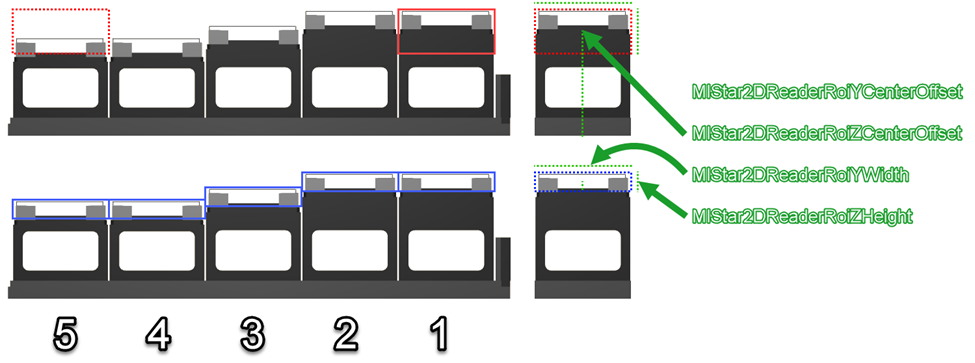
As we get to the end of this post I wanted to provide a bit more detail in visualizing what your labware properties mean in regards to barcode scanning:

When defining ROIs and light settings as labware properties you have two options: add a single set to the carrier OR add a set to each rack that needs to be scanned. Looking at the image above, the top carrier shows how you’d configure the properties on the carrier level with the bold red box being the final ROI. Notice how the window is taller in order to account for the plates in sites 2 through 5. Also notice how the MlStar2DReaderROIZCenterOffset is the distance from the bottom of the carrier to the middle of the ROI. This differs in comparison to the carrier on the bottom where each of the 5 racks have their own ROIs set. The MlStar2DReaderROIZCenterOffset for each rack on the bottom carrier in the image is the distance from the bottom of the plate to the middle of the ROI. The bottom carrier, not the racks on it, will need the labware property of MlStarCarOpenRasterBarcodePositions also specified. One final thing to note is that the MlStar2DReaderROIYCenterOffset in most cases will be 0, but can be positive or negative to move the horizontal position of the vertical dotted green line left or right, respectively.

And with that, happy barcode scanning.

Matt

7 Likes

Hi Eric, we are having what amounts to essentially the same issue as Pascal, we are using the
5 pos multiflex carrier with 5 base HP tabbed. Our custom ROI works for some locations but not all. We label our labware close to the base and these cannot be scanned with default settings at all, see my previous comment on the thread for reference. The main issue for us is that the custom ROI works on one of our carriers but not the other, see picture for reference. The custom ROI works on the left carrier but somehow it does not work at all on the right carrier, unless we move the labels up higher towards the top of the plate.


It is a bit concerning that a 2d barcode scanner that is image based can’t seem to handle custom barcode placement easily.

EDIT: we solved this issue by making sure the carrier properties had the BC orientation set to 2 (allow any orientation)