Volume of a round bottom segment is calculated incorrectly. The formula for the volume is correct. I wonder why the volume is incorrect and what formula is used by Venus to follow a liquid level during aspiration.
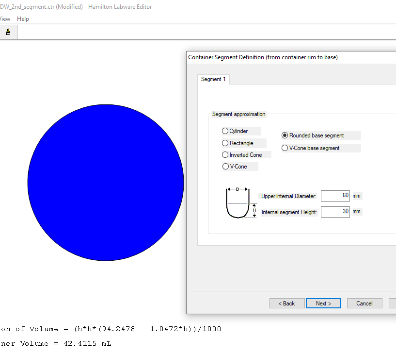
Below is an example of a container consisting of a single rounded base segment of a 60mm diameter and of a 30mm height.
The labware editor provides the correct formula, but a wrong volume: 42.4ml instead of 56.5ml:
2 Likes
@ivmikh - Discussion related to this topic, and other helpful context can be found in this forum post. I am not completely sure as to exactly why the reported volume for a rounded base segment is being underestimated by the labware editor application (compared to the theoretical volume based on face-value geometry), but this volume calculation (from labware editor) is not what VENUS uses at runtime to calculate liquid following, when that is toggled on.
Rather, VENUS does a separate calculation for liquid following distance based off of the starting height of the aspiration and the mixture of container segment geometries the requested volume.
More accurate techniques for using channels to measure and estimate remaining volumes in containers is discussed in the linked thread.
-Nick
1 Like
It is a pity that Venus doesn’t follow this formula, because the formula in the Labware Editor is correct. Moreover, for a segment with such a large diameter, a meniscus correction is negligible.
I appreciate you have provided a link to a relevant thread. However, the problem persists in this current thread:
Why does the Hamilton Labware Editor report an incorrect volume having got a correct formula for Volume(height)?
@ivmikh - There are proprietary considerations regarding channel and MPH liquid following speed when aspirating/dispensing in complex container segment geometries. I am unaware of any container type or liquid transfer that has proven to be in incompatible with slight deviations in tip submerge depth during portions of liquid following. Please let me know if you are experiencing issues, and we can take measures for support from there.
Regarding the incorrect estimate of volume reported by the labware editor for rounded base container segments, this has been reported to our software team. What I can say is this volume estimate is not used by VENUS outside of the labware editor window you have pointed out. It’s role is mainly to give the user feedback on their container definition, during the definition process.
-Nick
The linked forum post is no longer aviaible?
Question how does the Hamilton even internalize segment speeds if it is never passed to the instrument in the firmware command? Are segments even real? ZR parameter of the C0DS firmware command never seems to be sent from my testing with many segments. I do not know if I can post a screen shot of the firmware manual.
After our testing segment acceleration is backwards. Where larger segments the pipette speeds up pipetting and smaller segments the pipette is slowing down. For larger containers this causes us to loose tracking, not aspirating the full amount.
It feels like something with segments is either very wrong, or they are not used. This is kind of a big deal as how can you build a correct labware if the volume calculation in labware editor is not representative of what the instrument is calculating?
Here’s the corrected link, links from before 2024 seem to be broken due to the URL change
Some further clarification in the post linked below. Let us know what geometry of container you have defined so we can best assist!
1 Like
Super interesting! I don’t see this noted in the programmers manual or star manual. It would probably be a good heads up!
I had always assumed the reason for making more segments was to improve liquid following accuracy. We have some square wells with significant taper which started off this whole exploration. The only way to make a tapered square well is by adding segments, which then didn’t translate to liquid following speed.
We found the more segments the less accurate liquid following became!
1 Like
Agreed, and let me provide some further detail:
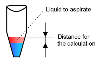
Case 1
The liquid is only in the conical part (segment 2) of the tube. Only the geometry of segment two (the conical shape) will be taken into account for the calculation of the liquid following speed. The speed is calculated from the height of the amount of liquid that will be removed.
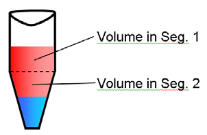
Case 2
The liquid is in both segments of the tube. The calculation of the liquid following speed is a mixture of the amount of liquid in segment one and the amount of liquid in segment 2. An average speed is calculated that suits both segments. The result is a slightly deeper submerge depth in the cylindrical part.
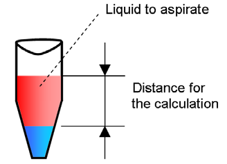
Case 3
If Liquid Level Detection is not used, the liquid following speed will be calculated from the given fixed height above the well bottom where the aspiration should start with the known geometry of the tube. The system can calculate if this is a Case A or B:
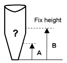
5 Likes
This is huge, we’ve been stumped with our results. This clears up a ton of our questions. Thank you!
3 Likes
Was the incorrect volume being displayed fixed in the “new” labware editor by any chance?

Hey Eric,
Wanted to confirm this is how the dispense tracking speed is calculated as well? Our aspiration tracking seems to be “ok” on our Eppendorf 1.5mL tubes (similar geometry to your picture), but then when they dispense at different heights they seem to lag behind quite a bit and not keep a 2mm tracking distance.
Also is there anyway to trace/access/see this internally calculated speed?
On further inspection it appears that these errors only occur in our v-cone segment of labware. Would really like to check the tracking speed, or if there are known issues with tracking in v-cones?
Hi @cwehrhan ,
Does your tube definition have 2 or 3 segments? The liquid following is calculated based off the first 2 segments it encounters. For aspiration, that could potentially be from the top segment to the second segment (for Eppendorf 1.5mL this is typically the cylinder into the v-cone). For dispense, this interaction is in reverse (bottom to top). I’m wondering if you have the round bottom segment still in the definition which is skewing the calculation leading to the slower following (smaller travel distance). Our recommendation would be to have a max of 2 segments for containers.
There isn’t a way to trace out this calculation, but the com trace file will have it in the parameter (fp param per channel). Aspirate commands are C0AS and dispense commands are C0DS, so if you search for those commands and compare your pipetting time from the trace file you can see what the fp value is being used for the transfer.
A note on this: fp is the travel distance, not the speed. The timing of the transfer is calculated from the volume/flow rate.
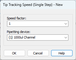
Something you can do to subtly tweak the liquid following without changing the container file is to use the Tip Tracking Speed (Single Step) command (you usually have to unhide this command in the system configuration editor). This factor affects how the fp parameter is calculated. Factor of 0.5 would half the value and a factor of 2.0 would double the value resulting in the tracking either slowing or speeding up with a factor of 1.0 using the default calculation. For the dispense, you can set the factor to 1.5 or 1.75 and see if this is enough dial in the liquid following for only the dispense. Just make sure to set it back to 1.0 after the command.
1 Like