Does anyone have .stl files for Hamilton-compatible carriers?
These things are $500+ on the used market and are only compatible with certain types of modules. They are a significant cost if you need to buy different ones to test new processes.
Has anyone successfully modeled & printed one before?
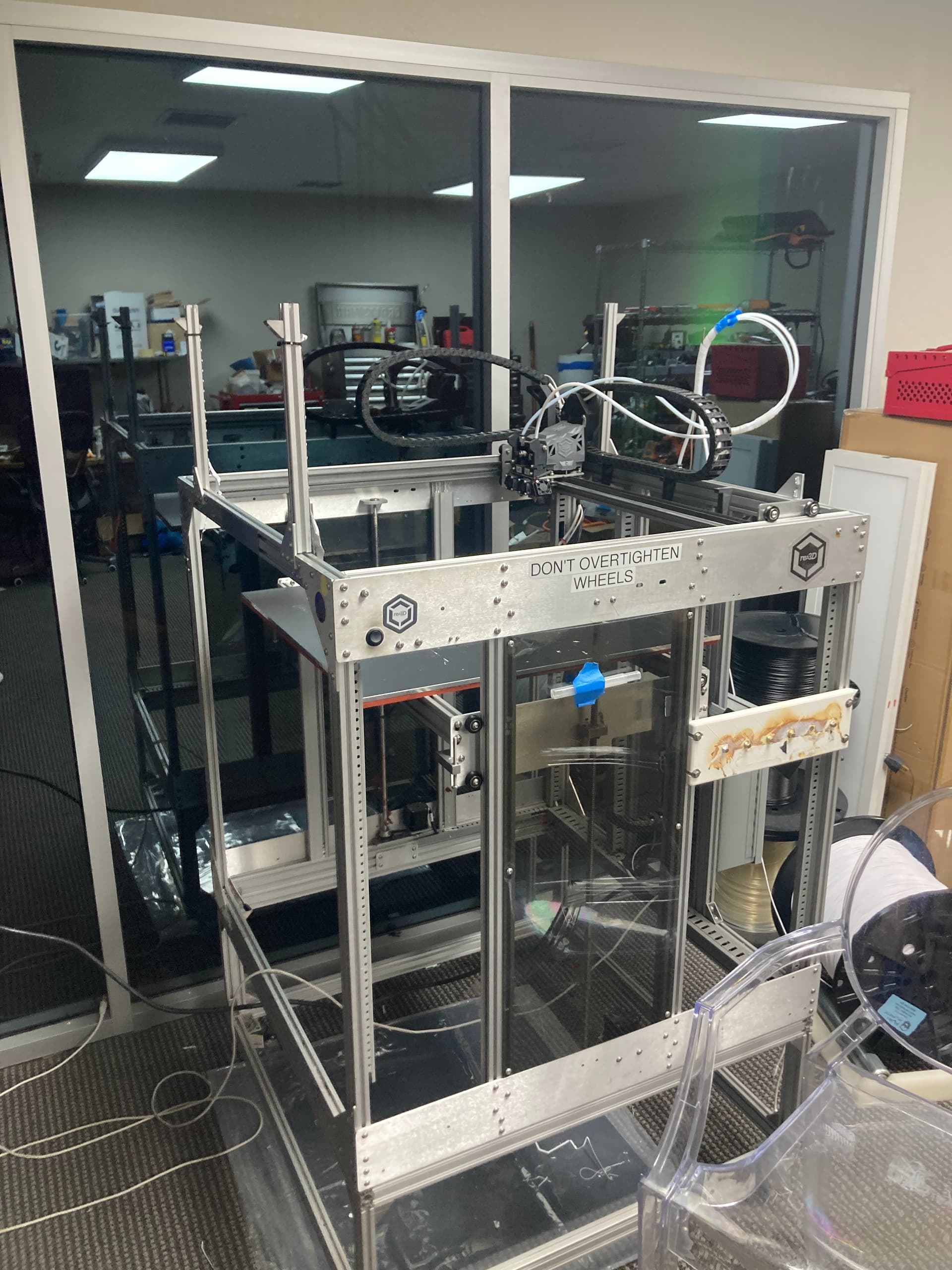
Printing a full carrier might be tough given the size and bed volume limitations for most 3d printers unless you’ve got a rather large one.
I imagine it might be easier to find a model for a universal SBS nest, print a few of those, and then find a way to mount them on some rails that are compatible with the torpedoes. Some of the opentrons folks might be able to help with that first part.
You can make custom .tml files in Venus Labware editor
Important to mention: We are new to the hamilton universe & don’t actually know what’s out there we can buy. Right now it feels more simple to design & print what we need to quickly bring up new processes instead of tracking everything down, waiting for shipping delays, etc.
How many hamilton shops just have a CNC machine onsite? For $20k it is certainly worth the cost.
You’re right we should have a standard .stl for interfacing with the torpedoes + something for modular mounting on top. Adaptors for tilt modules, heater-shakers, entire plate stackers, and more could all be printed. We save a few hundred $$$ each time we want to do something new, and can move faster.
Nice machine! The issue with printing complete carriers is that they will not retain enough precision to slide into and interface with the unit properly.
There is also a conductivity issue as all carriers ground along the backplane, via a small metal clip, when they are placed in the machine for CLLD (Capacitive Liquid Level Detection).
It might be possible to 3D print a carbon infused type material to assist with that.
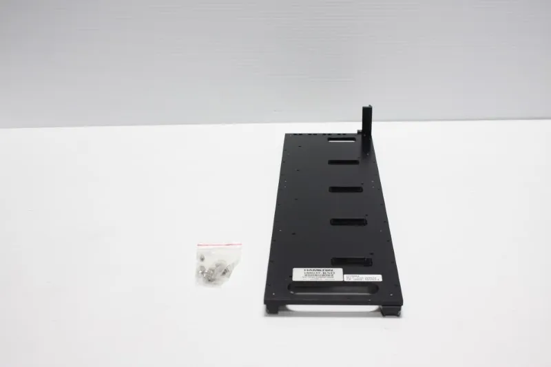
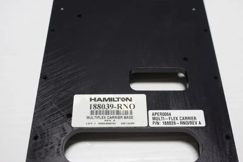
I would recommend having a look at their multi-flex carrier offerings. It is mostly all machined AL and reconfigurable. Nothing very complicated about them either.
I did not know that! We need to electrically ground all labware if we want CLLD working properly? That’s crazy. Quick solution is just running grounding wires from labware to grounding screws along backplane
Do you know how low-level I need to go to know whether or not I’m messing up the CLLD while I build custom labware, etc? I imagine there is probably some firmware command I sent to the robot where I’ll learn if this is working properly.
On a slightly related note: How do we, as engineers, move quickly building custom solutions for new processes? Right now it seems like there is a lot of superstition, uncertainty whether or not something will break. Even when the thing we’re building is extremely simple physically/mechanically.
The best way to verify if the LLD is going to work is by trying it out. I have created 3D printed items that have been placed directly on the deck where the CLLD was fine. I’ve also had others that didn’t work at all.
I prefer to take the SpaceX approach. Fail early and often. Also the added benefit of 3D printing is that it is great for fast iterative prototypes/mockups where the final piece will likely be made of sterner stuff.
I don’t believe that the carriers need to be electrically grounded. If that were the case cLLD wouldn’t work with most labware since the plate itself is a barrier between the sample and the carrier which would prevent a complete circuit.
The sensor in the back is simply a magnet that detects whether or not a carrier is present and helps with making sure the deck is loaded properly.
I’ve spoken with Hamilton about getting CAD files for instruments to help with system layout modeling, and while they’re pretty reluctant, they should be willing to do it if you provide an NDA.
Don’t know how I forgot about this before, but getting a Multiflex Base would be a one-time cost that would allow you to mount custom nests/accessories using hex screws.
This would let you get things on the robot without needing to precisely align with the torpedoes. Also has a little post in the back that houses the magnet.
Now that I think about it I might buy a few APE MFX carriers to try this out myself…
Have a look at the rear of all the carriers. They all have a small metal contact that grounds the carrier. These also exist on their larger plastic carriers which also have contact springs under the plate locations.
I believe it is about grounding the potential of the carrier as a whole. Another important reason is static charge dissipation. If the tips/carriers are isolated and carry a static charge, the tips have a tendency to float and dance on the channel ends after being ejected.
I have recently designed a 3D printable carrier system that’s very similar to the Hamilton Multiflex system.
I can confirm cLLD is not an issue.
I am still thinking about in which form I will share the designs. But I can post a few pictures after the holidays.
Material cost is about 50 euros for a full carrier so much much cheaper than a Hamilton carrier.
This is fantastic! I look forward to seeing your designs.
I would still advise some caution to others who may be using different fluids or materials. CLLD can be a tricky thing in some cases. Thankfully pLLD is also and option.
@LukeWitt 's suggestion is a really good one. The multiflex base carrier is a precision machined part and is going to give you a flexible and durable option for mounting 3D printed hardware. It also has “tracks” so you can pull it in/out and scan items using the built in scanner.
Also interested in @benjaminwohl 's carrier system! My recommendation would be to purchase or print the base carrier, and then build on top of that…
Having a library of 3D printer files for Hamilton (and other robot) deck resources would be sooo great, I’d love to pitch in to make something like that happen
@Stefan
Would anyone happen to know if there is an SLAS standard around this part? It feels like something that should be listed near the microplates on the SLAS site below, unless the company specifically owns that spec: ANSI/SLAS Microplate Standards